In-memory database system

a database system and database technology, applied in the field of in-memory database system, can solve the problems of limiting the level of concurrency and the total throughput of the system, not being a reason to keep rows clustered in memory, and unable to achieve maximum performance on current and future servers, etc., to achieve efficient scaling across a large number of processors

Active Publication Date: 2011-10-13
MICROSOFT TECH LICENSING LLC
View PDF26 Cites 99 Cited by
  • Summary
  • Abstract
  • Description
  • Claims
  • Application Information

AI Technical Summary

Benefits of technology

[0003]Many database systems have storage engines that were designed assuming that data would be stored on disk and frequently paged in and out of memory. Main memories are becoming large enough that many databases can be stored entirely in memory. Furthermore, there is a trend toward more processors (CPU cores) in modern computer systems, which may increase the need to efficiently scale across a large number of processors.
[0004]The present disclosure describes an in-memory database system (e.g., a database stored entirely in a main memory of a computer system) designed for modern multi-processor computer systems. The in-memory database system is designed to improve efficiency, to allow a high degree of concurrency, and to provide full transaction support for modern multi-processor computer systems. For example, the in-memory database system may avoid bottlenecks associated with commonly accessed data structures such as locks and latches. Full transaction support may include atomicity, consistency, isolation, and durability (e.g., ACID) support.

Problems solved by technology

Existing in-memory storage engines are unlikely to achieve maximal performance on current and future servers (e.g., multi-core machines).
This may limit the level of concurrency and the total throughput of the system (e.g., the locks and latches may become bottlenecks).
A third consequence is that, without a buffer pool, there may not be a reason to keep rows clustered in memory in the same page format used on disk.
Rows stored on pages may cause a number of difficulties.
For in-memory lookup, B-Trees may not be the most efficient data structure available, so there may be a performance penalty associated with this layout.
Moreover, page re-arrangement, splits and merges may lead to rows being moved around such that rows can no longer be identified and de-referenced by virtual address.
Transactions may be aborted due to errors, commit dependencies, or another reason.

Method used


Image

  • In-memory database system
  • In-memory database system
  • In-memory database system

Examples


Embodiment Construction

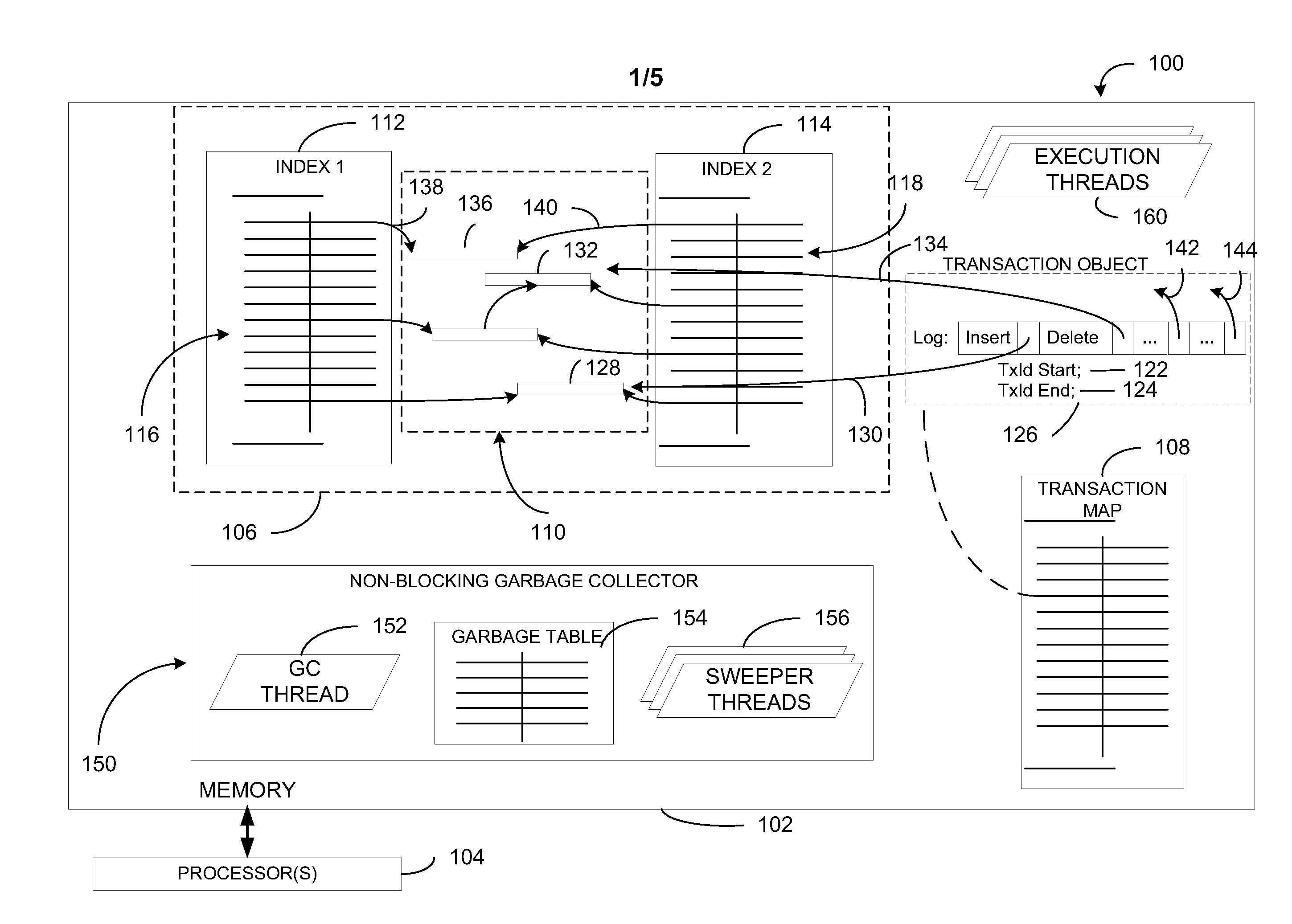
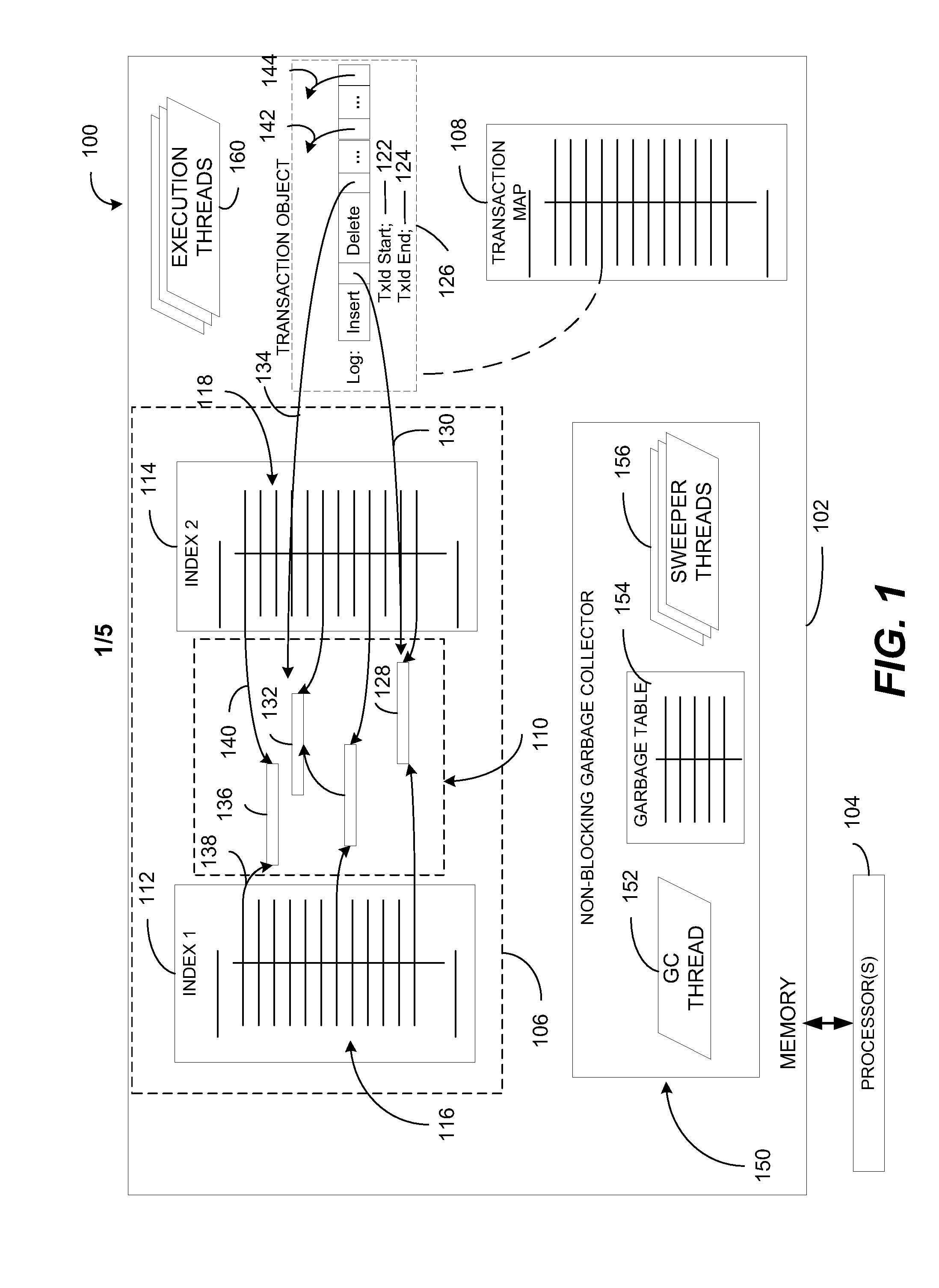
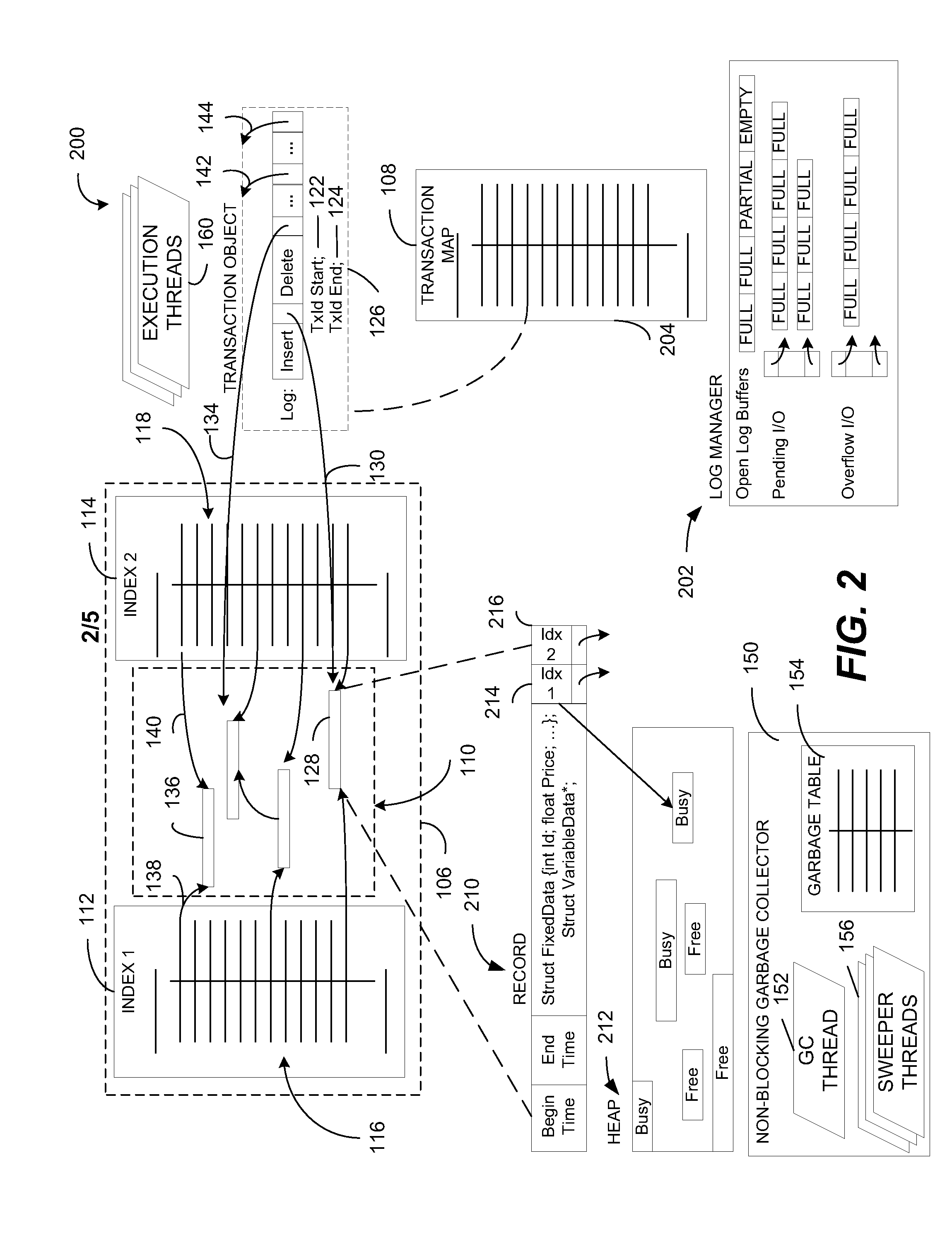
[0012]In a particular embodiment, a computer system is disclosed that includes a memory and a processor coupled to the memory. The processor is configured to execute instructions that cause execution of an in-memory database system that includes one or more database tables. Each database table includes a plurality of rows, where data representing each row of the plurality of rows is stored in the memory. The in-memory database system also includes a plurality of indexes associated with the one or more database tables. Each index of the plurality of indexes is implemented by a lock-free data structure. The in-memory database system further includes update logic configured to update a first version of a particular row to create a second version of the particular row. The in-memory database system also includes a non-blocking garbage collector configured to identify and deallocate data representing outdated versions of rows. These features enable the database system to execute a transa...


PUM


Abstract

A computer system includes a memory and a processor coupled to the memory. The processor is configured to execute instructions that cause execution of an in-memory database system that includes one or more database tables. Each database table includes a plurality of rows, where data representing each row is stored in the memory. The in-memory database system also includes a plurality of indexes associated with the one or more database tables, where each index is implemented by a lock-free data structure. Update logic at the in-memory database system is configured to update a first version of a particular row to create a second version of the particular row. The in-memory database system includes a non-blocking garbage collector configured to identify data representing outdated versions of rows.

Description

BACKGROUND[0001]Many database systems include storage engines that were designed based on the assumption that data is stored on a disk and paged in and out of main memory when required for processing. As a result of the growth in main memory capacity, it may be possible to store many databases entirely in memory. Furthermore, there is a trend toward more processors (i.e., central processing unit (CPU) cores) in computer systems.[0002]Existing in-memory storage engines are unlikely to achieve maximal performance on current and future servers (e.g., multi-core machines). Existing in-memory storage engines use one or more frequently accessed data structures and protect shared data by locks and latches. This may limit the level of concurrency and the total throughput of the system (e.g., the locks and latches may become bottlenecks).SUMMARY[0003]Many database systems have storage engines that were designed assuming that data would be stored on disk and frequently paged in and out of mem...

Claims


Application Information

Patent Timeline
Patent Type & Authority Applications(United States)
IPC IPC(8): G06F17/30G06F7/00
CPCG06F17/30501G06F16/2379G06F16/27G06F16/219G06F16/24561G06F12/0253G06F2212/1044
Inventor DIACONU, CRISTIANFREEDMAN, CRAIG STEVENLARSON, PER-AKEZWILLING, MICHAEL JAMES
Owner MICROSOFT TECH LICENSING LLC
Why Eureka
Try Eureka