Canister arrangement structure, fuel vapor recovery device, and vehicle equipped with fuel vapor recovery device

a technology of fuel vapor recovery and canister arrangement, which is applied in the direction of machines/engines, mechanical equipment, separation processes, etc., can solve the problems of long pipeline connecting the fuel tank and the canister to each other, and increase in the size of the fuel vapor recovery devi

Active Publication Date: 2011-10-20
TOYOTA JIDOSHA KK
View PDF15 Cites 4 Cited by
  • Summary
  • Abstract
  • Description
  • Claims
  • Application Information

AI Technical Summary

Benefits of technology

[0014]The invention provides a canister arrangement structure, a fuel vapor recovery device, and a vehicle equipped with the fuel vapor recovery device that can restrain a fuel tank from being warmed by the heat of exhaust gas flowing through an exhaust pipe while warming an adsorbent built in a canister with the aid of the heat of the exhaust gas flowing through the exhaust pipe.

Problems solved by technology

However, when such a construction is adopted, the canister is increased in size and leads to an increase in the size of the fuel vapor recovery device.
However, when this construction is adopted, the pipeline connecting the fuel tank and the canister to each other is long.
Further, the space in which the fuel tank and the exhaust pipe can be arranged is limited.
In some cases, therefore, a sufficient distance cannot be ensured between the fuel tank and the exhaust pipe.

Method used


Image

  • Canister arrangement structure, fuel vapor recovery device, and vehicle equipped with fuel vapor recovery device
  • Canister arrangement structure, fuel vapor recovery device, and vehicle equipped with fuel vapor recovery device
  • Canister arrangement structure, fuel vapor recovery device, and vehicle equipped with fuel vapor recovery device

Examples


first embodiment

[0026]A first embodiment of the invention in which a canister arrangement structure according to this invention is embodied in a fuel vapor recovery device mounted on a vehicle will be described hereinafter with reference to FIGS. 1 to 3.

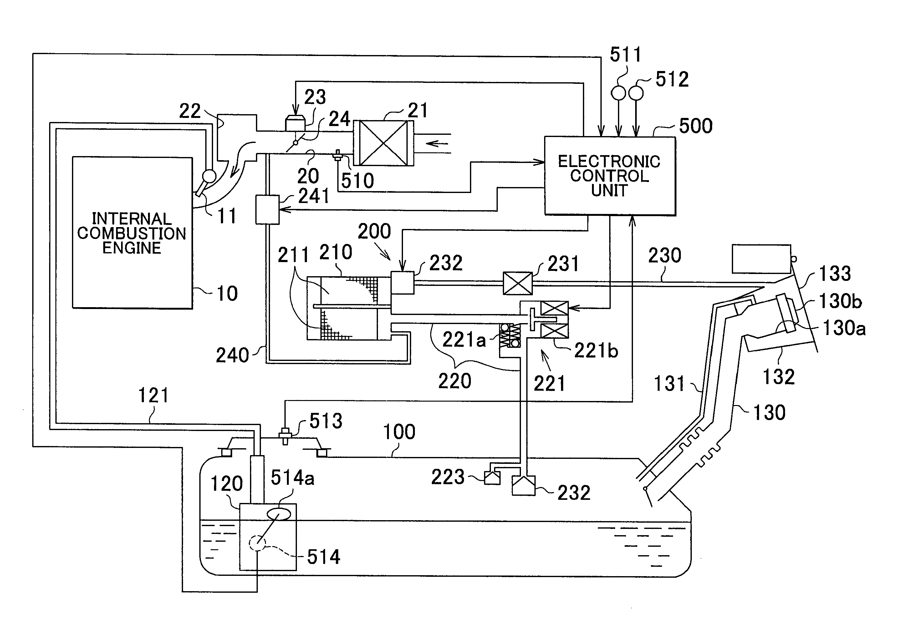
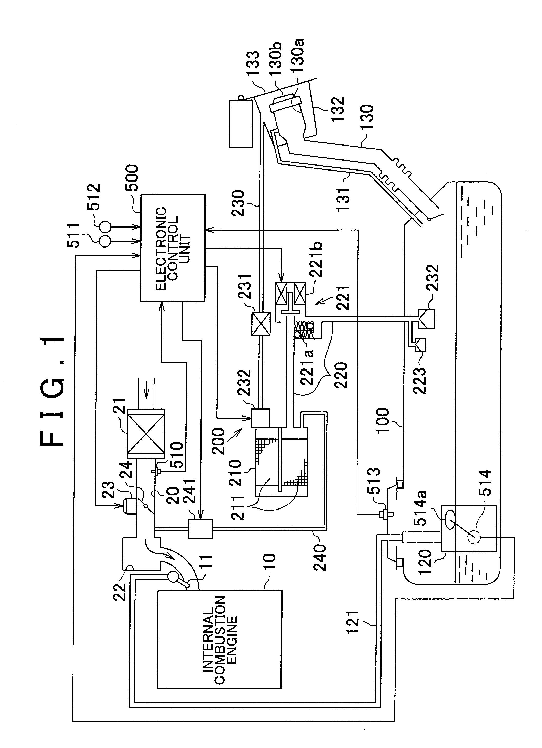
[0027]FIG. 1 shows an overall construction of a fuel vapor recovery device 200 according to this embodiment of the invention. As shown in a lower region of FIG. 1, a fuel tank 100 is provided with a pump module 120 that pumps up fuel stored in the fuel tank 100. Further, the fuel tank 100 is provided, in an upper portion thereof, with a pressure sensor 513 that detects a pressure in the fuel tank 100.

[0028]The pump module 120 is connected to a fuel injection valve 11 of an internal combustion engine 10 via a fuel supply pipe 121. Thus, the fuel pumped up from the fuel tank 100 by the pump module 120 is supplied to the fuel injection valve 11 through the fuel supply pipe 121. It should be noted that the pump module 120 is provided with a fuel sender ...

second embodiment

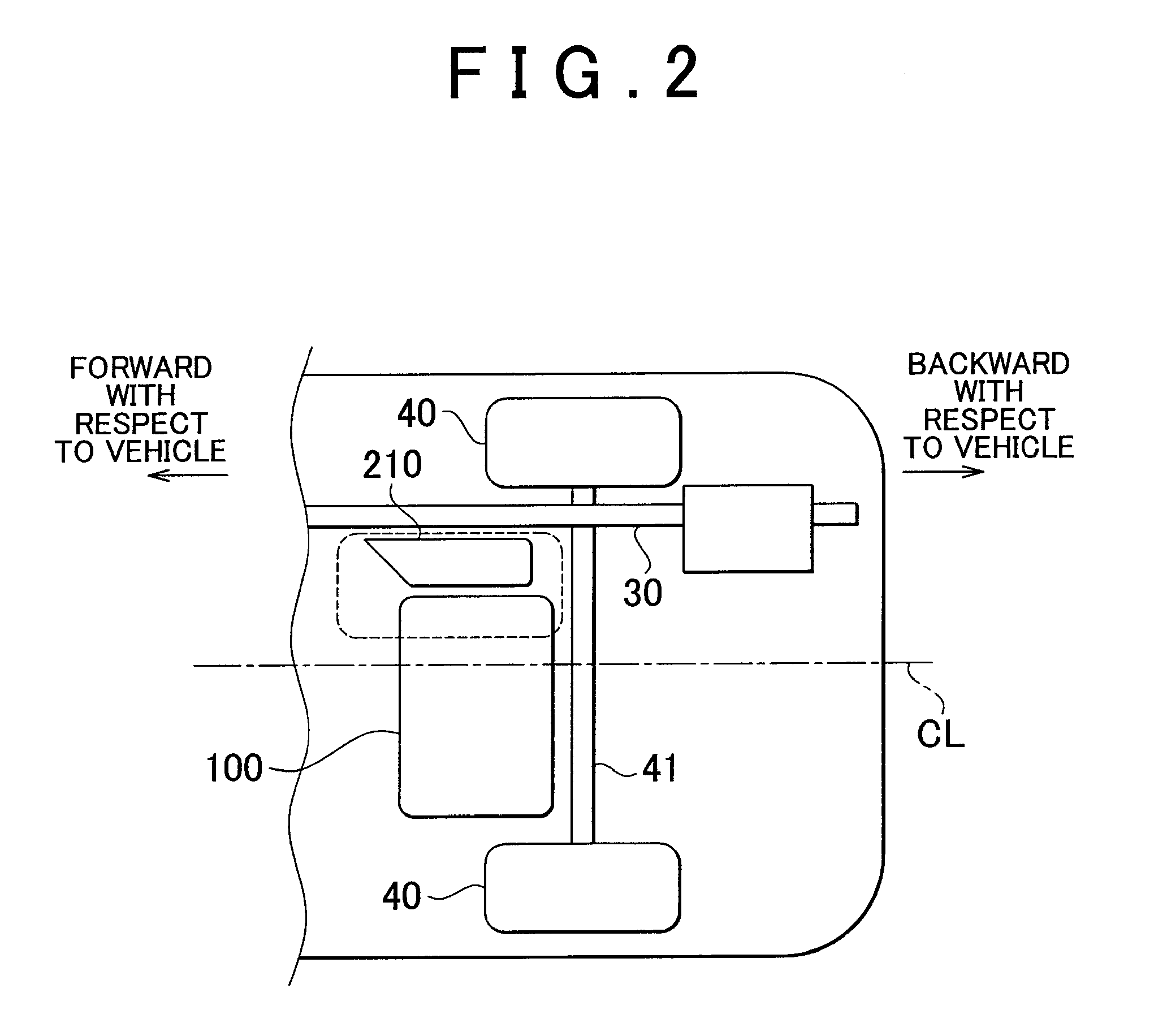
[0075]A second embodiment of the invention in which a canister arrangement structure according to this invention is embodied in a fuel vapor recovery device mounted on a vehicle will be described hereinafter with reference to FIGS. 5 and 6. It should be noted that FIG. 5 is a schematic view showing an arrangement position of the canister 210 in the fuel vapor recovery device 200 according to the second embodiment of the invention, and that FIG. 6 is a schematic view showing the exhaust pipe 30, the fuel tank 100, and the canister 210 according to this embodiment of the invention as viewed from a position beside the vehicle.

[0076]It should be noted that the vehicle according to the second embodiment of the invention is different from the vehicle according to the first embodiment of the invention in the arrangement mode of the exhaust pipe 30 and the arrangement mode of the canister 210. The fuel vapor recovery device 200 according to this embodiment of the invention is identical in b...


PUM


Abstract

A canister arrangement structure in a fuel vapor recovery device includes a canister that has built therein an adsorbent for adsorbing fuel and temporarily collects fuel vapor generated in a fuel tank of an internal combustion engine, the canister is arranged between an exhaust pipe of the internal combustion engine and the fuel tank.

Description

INCORPORATION BY REFERENCE[0001]The disclosure of Japanese Patent Application No. 2010-097012 filed on Apr. 20, 2010, including the specification, drawings and abstract is incorporated herein by reference in its entirety.BACKGROUND OF THE INVENTION[0002]1. Field of the Invention[0003]This invention relates to a canister arrangement structure in a fuel vapor recovery device that treats fuel vapor generated in a fuel tank after temporarily collecting the fuel vapor into a canister, the fuel vapor recovery device, and a vehicle equipped with the fuel vapor recovery device.[0004]2. Description of the Related Art[0005]In a fuel tank in which liquid fuel is stored, fuel vaporizes from a liquid surface of the fuel stored in the fuel tank, so that fuel vapor is generated in the fuel tank. A vehicle mounted with an internal combustion engine or the like is mounted with a fuel vapor recovery device that introduces fuel vapor generated in a fuel tank into an intake passage of the internal comb...

Claims


Application Information

Patent Timeline
Patent Type & Authority Applications(United States)
IPC IPC(8): B01D53/04F01N3/00
CPCF02M25/089
Inventor OGAWA, YOSHIHIDE
Owner TOYOTA JIDOSHA KK
Why Eureka
Try Eureka