Narrow Graphene Nanoribbons from Carbon Nanotubes

Active Publication Date: 2011-10-20
THE BOARD OF TRUSTEES OF THE LELAND STANFORD JUNIOR UNIV
View PDF1 Cites 55 Cited by
  • Summary
  • Abstract
  • Description
  • Claims
  • Application Information

AI Technical Summary

Benefits of technology

[0026]In certain aspects, the present invention comprises a method wherein said treating said exposed strip comprises contacting the exposed strip with plasma. The plasma may be argon plasma. The plasma may be a low po

Problems solved by technology

Currently, making pristine GNRs using lithographic, chemical or sonochemical methods is challenging.
Lithographic patterning has been used to produce wide ribbons (>20 nm) from graphene sheets (Chen et al 2007 Physica E 40: 228; and Han et al 2007 Phys. Rev. Lett. 98: 206805), but the width and smoothness of the GNRs were limited by the resolution of the lithography and etching techni

Method used


Image

  • Narrow Graphene Nanoribbons from Carbon Nanotubes
  • Narrow Graphene Nanoribbons from Carbon Nanotubes
  • Narrow Graphene Nanoribbons from Carbon Nanotubes

Examples


example 1

Preparation of GNRs

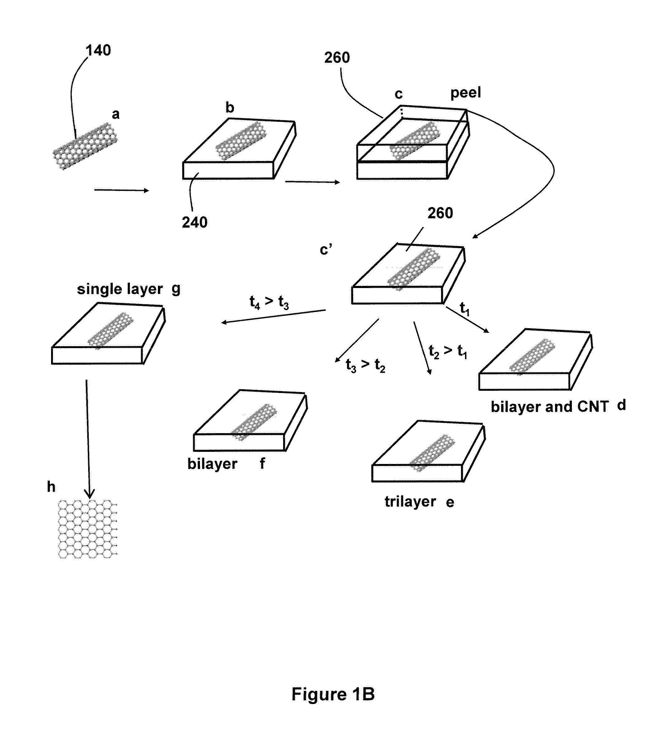
[0088]1 mg of MWNTs was dispersed in 10 ml of 1% Tween 20 aqueous solution by sonication for 5 min and then centrifugation at 16,400 g for 10 min to remove aggregates. The MWNT suspension was deposited onto a Si substrate pretreated with 3-aminopropyltriethoxysilane (APTES, 12 ml in 20 ml of H2O), rinsed with water and then blow-dried. The sample was then calcined at 350° C. for 10 min to remove the Tween 20. A PMMA solution (relative molecular mass, Mw 5495,000; 5% in anisole) was spin-coated on MWNTs on the substrate at 3,000 rounds per minute for 1 min and then baked at 170° C. for 2 h on a hot plate. The PMMA-MWNT film was peeled off in 1M KOH solution at 80° C. (Jiao et al 2008 J. Am. Chem. Soc. 130:12612). Then the film was rinsed with water and contact-printed onto a Si substrate. To make the film well-adhered to the Si substrate, the sample was heated at 80° C. for 10 min in an oven. Ten-watt Ar plasma was used to etch the PMMA-MWNT film at the base pressu...

example 2

Histograms of Pristine MWNTs and GNRs

[0089]The diameter of more than 100 MWNTs (Bucky tube, Aldrich) on Si substrate was measured with atomic force microscopy (AFM). FIG. 3A shows the diameter distribution of pristine MWNTs. The distribution of diameters ranged from 4 to 18 nm and the mean diameter was ˜8 nm. Because of the difficulties of distinguishing multi-layer GNRs from GNRs with CNTs cores by AFM, only the widths and heights of single or few-layer GNRs were measured (height <2 nm). As shown in FIG. 3B, the widths of most GNRs were in the range of 10 to 20 nm. The heights of GNRs distributed around three discrete values, i.e., ˜0.8 nm, 1.3 nm and 1.8 nm (FIG. 3C), which were assigned to single, bi- and tri-layer GNRs, respectively. Most GNRs obtained were single and bi-layer.

example 3

Yield of Single- and Few-Layer GNRs

[0090]The yield of single and few-layer GNRs was determined by the diameter, number of shells of the starting MWNTs and the etching time. The yield of GNRs with high quality was ˜20% after etching for 10 s. By assuming that the width of GNRs was comparable with half of the circumference of the starting MWNTs, that GNRs with a width of 10-20 nm were estimated to be converted from MWNTs with a diameter of 6-12 nm. From the diameter distribution of MWNTs (FIG. 3A) ˜40% of pristine MWNTs had a diameter of 6-12 nm. However, the number of shells of MWNTs varied even with the same diameter and only few-walled CNTs could generate single or few-layer GNRs. Therefore, the yield of single and few-layer GNRs was much lower than 40%.


PUM


Abstract

Disclosed is a method for making graphene nanoribbons (GNRs) by controlled unzipping of structures such as carbon nanotubes (CNTs) by etching (e.g., argon plasma etching) of nanotubes partly embedded in a polymer film. The GNRs have smooth edges and a narrow width distribution (2-20 nm). Raman spectroscopy and electrical transport measurements reveal the high quality of the GNRs. Such a method of unzipping CNTs with well-defined structures in an array will allow the production of GNRs with controlled widths, edge structures, placement and alignment in a scalable fashion for device integration. GNRs may be formed from nanostructures in a controlled array to form arrays of parallel or overlapping structures. Also disclosed is a method in which the CNTs are in a predetermined pattern that is carried over and transferred to a substrate for forming into a semiconductor device.

Description

STATEMENT OF GOVERNMENTAL SUPPORT[0001]This invention was made with U.S. Government support under a grant from the United States Office of Naval Research, Grant # N00014-08-1-0860 and under contract HR0011-07-03-0002 awarded by DARPA. The U.S. Government has certain rights in this invention.CROSS-REFERENCE TO RELATED APPLICATIONS[0002]NoneREFERENCE TO SEQUENCE LISTING, COMPUTER PROGRAM, OR COMPACT DISK[0003]None.BACKGROUND OF THE INVENTION[0004]1. Field of the Invention[0005]The present invention relates to the field of materials and particularly to the field of graphene nanoribbons.[0006]2. Related Art[0007]Presented below is background information on certain aspects of the present invention as they may relate to technical features referred to in the detailed description, but not necessarily described in detail. The discussion below should not be construed as an admission as to the relevance of the information to the claimed invention or the prior art effect of the material describ...

Claims


Application Information

Patent Timeline
IPC IPC(8): H01L29/16H01L21/04B44C1/22B82Y30/00B82Y40/00
CPCB82Y30/00H01L51/0558H01L29/1606B82Y40/00Y10S977/882Y10S977/936Y10S977/89Y10S977/848Y10S977/888H10K10/484
Inventor DAI, HONGIEJIAO, LIYING
Owner THE BOARD OF TRUSTEES OF THE LELAND STANFORD JUNIOR UNIV
Why Eureka
Try Eureka