Resonant capacitor clamping circuit in resonant converter

a technology of resonant capacitors and clamping circuits, applied in the field of resonant converters, can solve the problems of disadvantageous clamping methods and functional hold-up, and achieve the effect of improving hold-up tim

Active Publication Date: 2011-10-20
DELTA ELECTRONICS (THAILAND) PUBLIC CO LTD
View PDF0 Cites 18 Cited by
  • Summary
  • Abstract
  • Description
  • Claims
  • Application Information

AI Technical Summary

Benefits of technology

[0010]It is the object of the invention to create a resonant converter pertaining to the technical field initially mentioned, that concurrently provides for limitation of the resonant capacitor voltage and the resonant current during overload or short circuit conditions as well as for improved hold up time in case of high output power.
[0016]Such a resonant converter has the advantage that during normal operating condition, hence without a hold up condition, the clamping capacitor is charged via the third and fourth diode to the bulk voltage of the voltage source. When the bulk voltage decreases due to a hold up condition, the voltage of the clamping capacitor remains constant, hence the hold-up time is extended. In case of an overload condition the voltage of the resonant capacitor is clamped to the voltage of the clamping capacitor. Because energy is transferred to the clamping capacitor, the voltage of the clamping capacitor rises during overload condition. The pulse control unit is designed such that the switching frequency is increased at an overload condition causing the resonant current to be reduced and hence the clamping of the resonant capacitor to disappear.
[0018]A discharge unit provides for resetting the voltage of the clamping capacitor and for reasonable operation of the resonant converter.
[0028]Preferably, a discrete inductor is connected in parallel to the transformer respectively a discrete first subpart of an inductor is connected to the first subpart of the transformer and a discrete second subpart of an inductor is connected to the second subpart of the transformer in order to define the at least one resonant inductance. Such a discrete inductor allows for more flexibility when designing the resonant converter.

Problems solved by technology

However, the described clamping method is disadvantageous for the boost characteristic of the converter used for hold up functionality.

Method used


Image

  • Resonant capacitor clamping circuit in resonant converter
  • Resonant capacitor clamping circuit in resonant converter
  • Resonant capacitor clamping circuit in resonant converter

Examples


Embodiment Construction

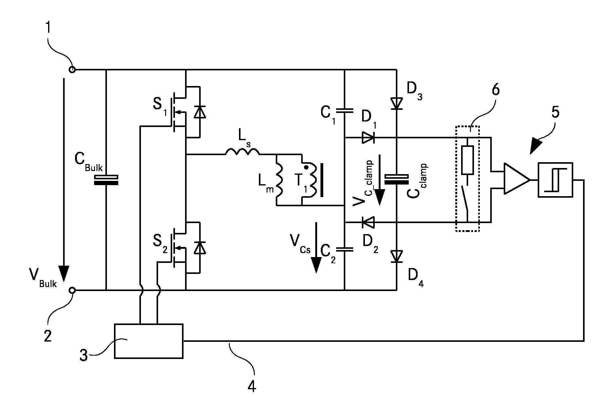
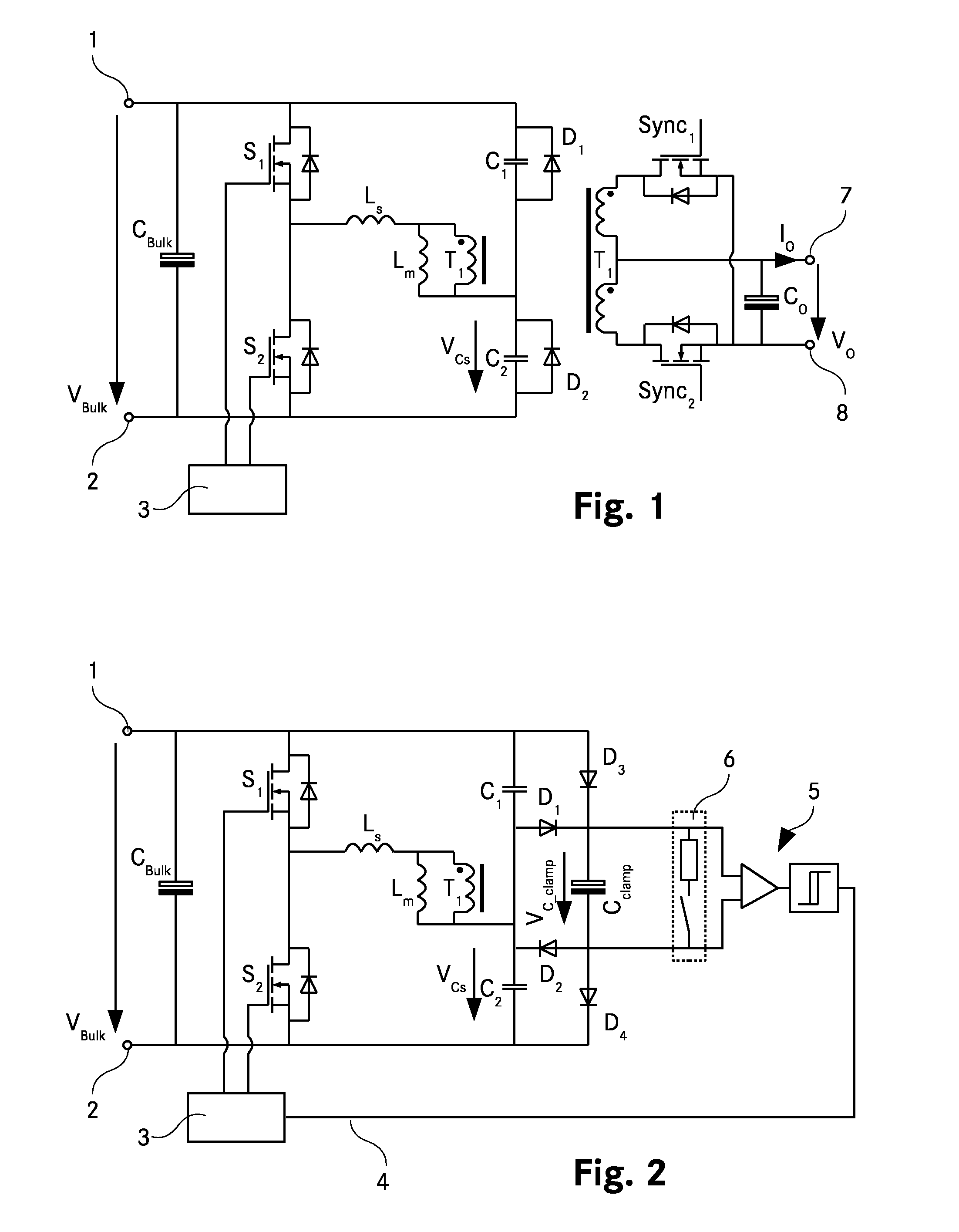
[0038]FIG. 1 shows a LLC resonant converter implementing the formerly known clamping scheme. A bulk voltage source VBulk is connected to a first and a second input terminal 1, 2 of the LLC resonant converter. Between the first and second input terminal 1, 2, a bulk capacitor CBulk, is connected. A first end of a first switch S1 is connected to the first input terminal 1 and a second end of the first switch S1 is connected to a first end of a second switch S2. A second end of the second switch S2 is connected to the second input terminal 2. Hence, the first and the second switch S1, S2 are connected in series, and both are connected in parallel to the bulk capacitor CBulk and the bulk voltage source VBulk. Further, again in parallel to the bulk capacitor CBulk and the first and the second switch S1, S2, a first end of a first resonant capacitor C1 is connected to the first input terminal 1, a second end of the first resonant capacitor C1 is connected to a first end of a second resona...


PUM


Abstract

A resonant converter comprises a first and a second input terminal (1, 2) in order to connect a voltage source (VBulk). The first end of a first switch (S1) is connected to the first input terminal (1). The second end of the first switch (S1) is connected to the first end of a second switch (S2). The second end of the second switch (S2) is connected to the second input terminal (2). A first end of a resonant circuit comprising at least one resonant inductance, at least one resonant capacitor (C1, C2, Cs), and at least a primary winding of a transformer (T1, T1<sub2>—< / sub2>a, T1<sub2>—< / sub2>b) is connected to the second end of the first switch (S1) and to the first end of the second switch (S2). A third diode (D3) is connected in conduction direction from the first end of the first switch (S1) to the first end of a clamping capacitor (Cclamp). A fourth diode (D4) is connected in conduction direction from the second end of the clamping capacitor (Cclamp) to the second end of the second switch (S2). A comparator (5) is connected to the first and second end of the clamping capacitor (Cclamp). The comparator (5) is connected to a pulse control unit (3) in order to control the first and the second switch (S1, S2).

Description

TECHNICAL FIELD[0001]The invention relates to a resonant converter, comprising a first and a second input terminal in order to connect a voltage source, wherein the first end of a first switch is connected to the first input terminal, wherein the second end of the first switch is connected to the first end of a second switch, wherein the second end of the second switch is connected to the second input terminal, wherein a first end of a resonant circuit comprising at least one resonant inductance, at least one resonant capacitor, and at least a primary winding of a transformer is connected to the second end of the first switch and to the first end of the second switch.BACKGROUND ART[0002]Resonant converters, in particular LLC resonant converters, have a growing popularity due to their high efficiency, low level of EMI emissions, and ability to achieve high power density. Further advantages are small size, light weight and high efficiency.[0003]Typical topologies of LLC resonant conve...

Claims


Application Information

Patent Timeline
Patent Type & Authority Applications(United States)
IPC IPC(8): H02M7/5387
CPCY02B70/1433H02M3/3382Y02B70/10Y02P80/10
Inventor FIGGE, HEIKOSCHAFMEISTER, FRANK
Owner DELTA ELECTRONICS (THAILAND) PUBLIC CO LTD
Why Eureka
Try Eureka