
Assembly for cooking elongated food products

a technology of elongated food products and assembly parts, which is applied in the direction of roasting apparatus, application, bakery products, etc., can solve the problems of general limited “food product shaping” and achieve the effect of facilitating the formation of cooked food products

Active Publication Date: 2011-10-20
CADENT
View PDF3 Cites 12 Cited by
  • Summary
  • Abstract
  • Description
  • Claims
  • Application Information

AI Technical Summary

Benefits of technology

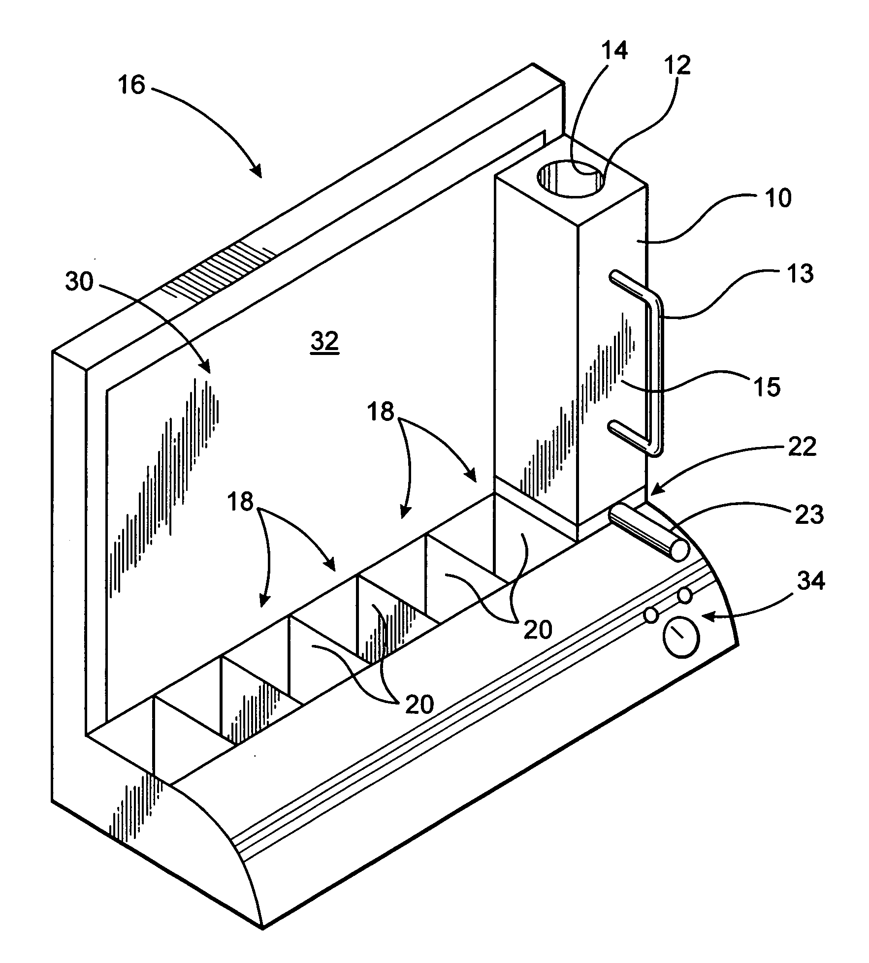
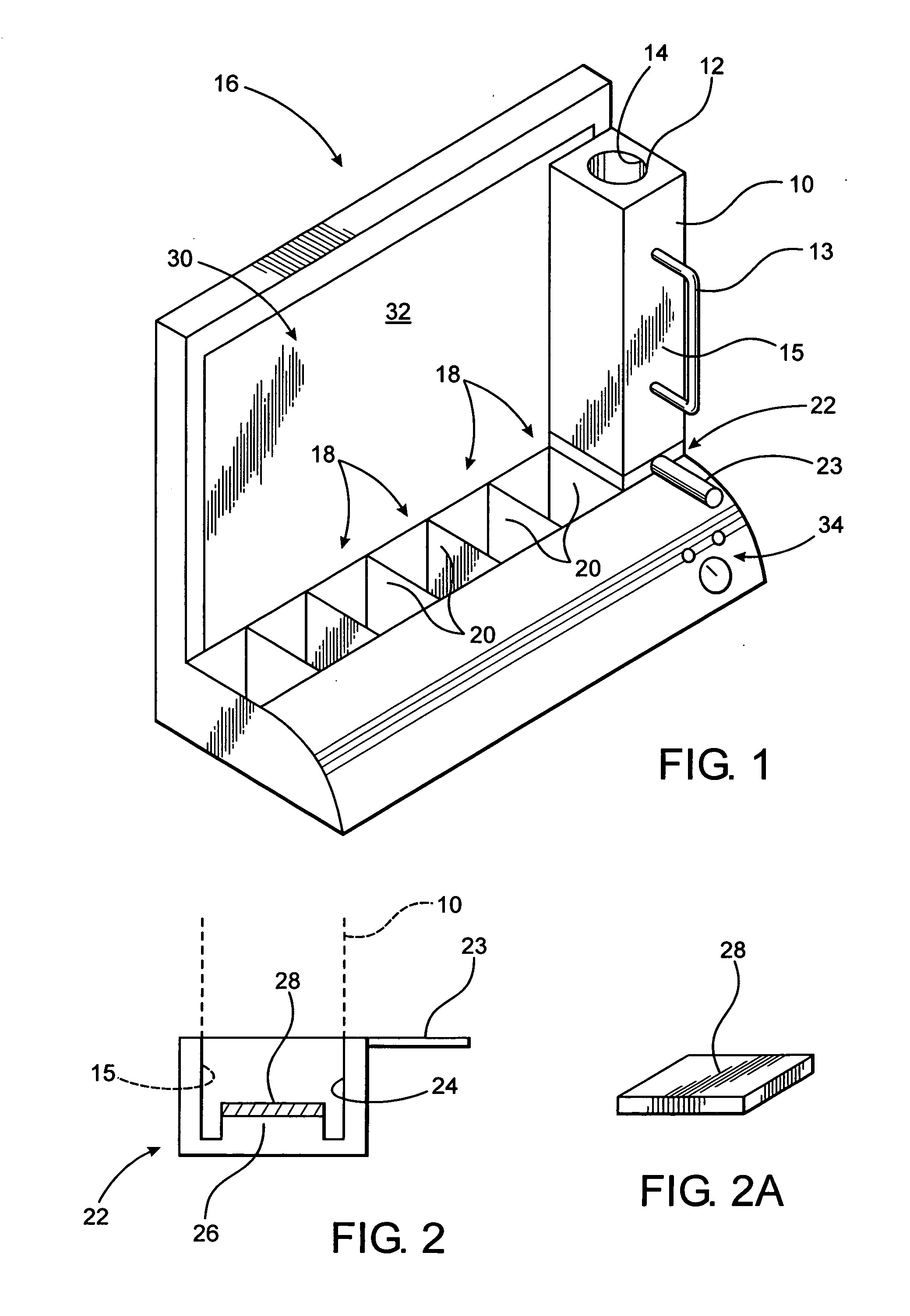
[0010]The present invention is directed to an assembly for cooking various types of food products in a substantially upright orientation utilizing at least one mold housing having an interiorly disposed mold chamber. Further, the upright orientation of the mold housing and mold chamber during the cooking procedure facilitates the formation of the cooked food product into a configuration which substantially corresponds to the internal dimensions and configuration of the mold chamber in which it is cooked.
[0012]The versatility of the cooking assembly of the present invention is evidenced by a plurality of possible structural modifications or embodiments utilized to form one or concurrently a plurality of cooked food products with a predetermined and / or customized shape. Accordingly, the various embodiments of the cooking assembly of the present invention include one or more mold housing, each being at least partially formed of a heat transferable material and including at least one food mold chamber integrally or removably disposed on the interior thereof. Further, a plurality of such mold housings may be structured to be operatively connected to and / or supported on a frame assembly, wherein a plurality of food products may be simultaneously or independently cooked. Operative and structural features of the various embodiments also include a heat source integrated into the frame assembly being structured to concurrently or independently expose each of the mold housings and associated mold chambers to an adequate amount of heat to cook the food compositions contained therein. In at least one embodiment, at least the frame assembly is insulated to increase the heat transfer efficiency through the mold housing and mold chamber to the food composition to be cooked. In yet one further embodiment, the insulated frame assembly serves to protect users from extreme temperature on the exterior of the device.
[0013]Yet additional embodiments of the cooking assembly of the present invention include a single mold housing having a plurality of mold chambers integrally formed therein or removably connected thereto, such that either homogeneous or non-homogeneous food compositions may be introduced into different ones of the plurality of mold chambers. Moreover, the mold housings and associated plurality of mold chambers may be concurrently exposed to a common heat source which may be associated with a cooperatively structured frame assembly or incorporated directly into the mold housing(s) itself. In at least one embodiment, the heat source comprises a temperature controlled bath containing an amount of a heat transfer fluid which may be maintained at an optimal cooking temperature for a given food composition.
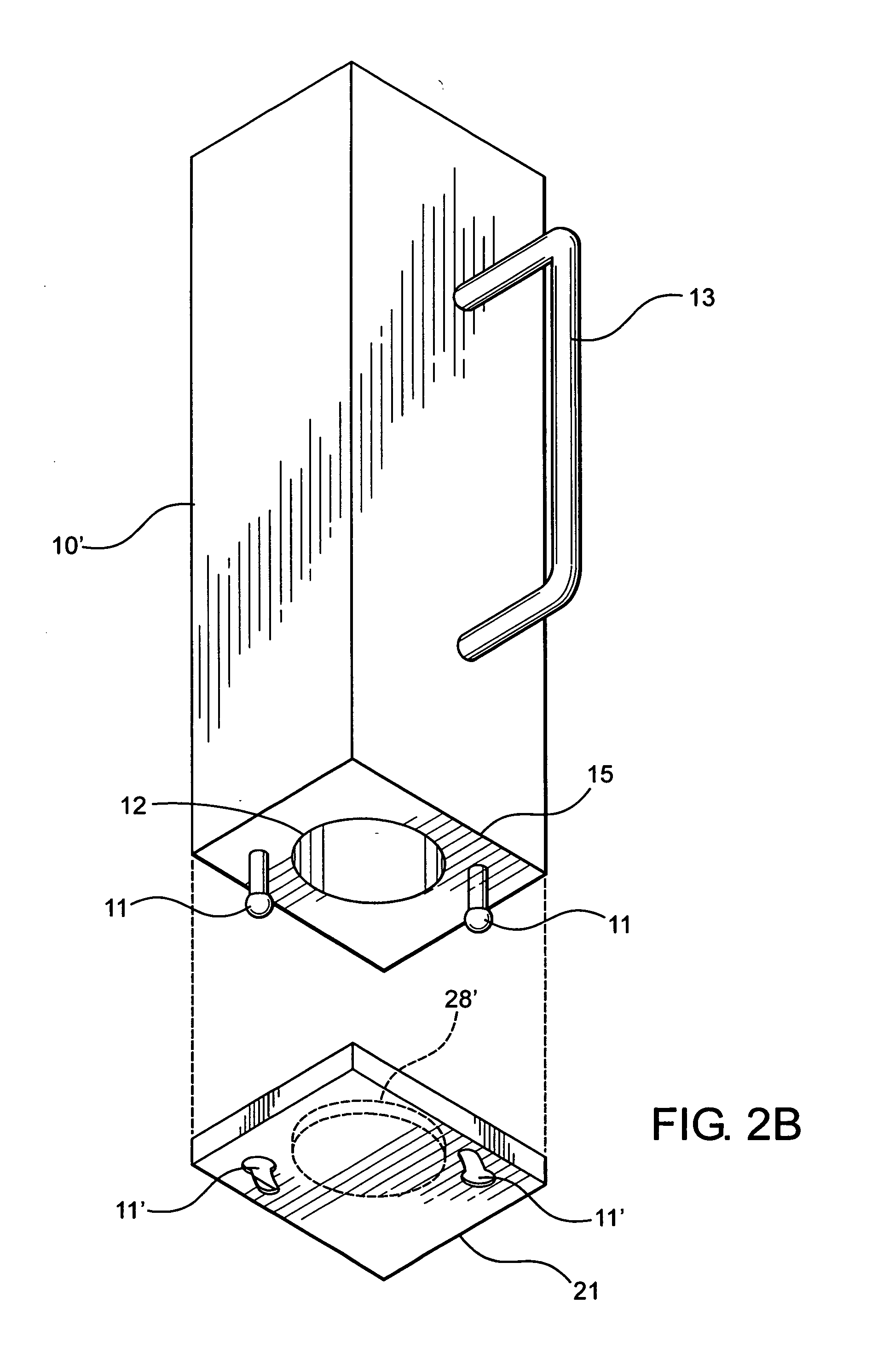
[0015]In use, the liquid or fluid like consistency food composition is introduced into the interior of one or more mold chambers by a flow directing structure such as, but not limited to, a funnel or other insertion device. Before filling of the mold cavity at least the lower open end thereof is closed and at least partially sealed, at least to the extent of substantially restricting leakage of the liquid food composition from the lower end of the mold cavity. The aforementioned heat source is activated and the one or more mold chambers associated with the one or more mold housings are exposed to a heat sufficient to accomplish cooking and, accordingly, at least partial solidification of the food product.
[0016]Once cooked, various structural features associated with the mold housing facilitate a removal of the cooked food product without damaging it or significantly altering the intended configuration thereof. Moreover, the cooked food product may be removed from corresponding ones of the mold chambers by movably interconnecting sections of the mold housing to one another so as to define a substantially “clamshell” structure. At least partial separation of the mold housing sections is thereby possible so as to easily access the cooked food product within the mold chamber. Alternatively, various devices can be utilized to physically remove the cooked food product without causing damage thereto, as explained in greater detailed hereinafter. Other additional features associated with the various embodiments of the cooking assembly of the present invention may include a venting assembly structurally adapted to accommodate the release of pressure or vacuum which may build up in a mold chamber during a cooking procedure in the various structural embodiments of the mold housings and / or associated mold chambers. Such venting assemblies are structured to release excessive pressure, such as by venting steam, evaporated fluid, heated air, etc., or by breaking a vacuum which may be created between a cooked or semi-cooked food composition and the mold housings and / or associated mold chambers.
[0017]Therefore, the cooking assembly of the present invention satisfies the needs and desires which may be associated with domestic as well as commercial preparation of relatively uniquely shaped cooked food products, wherein the food products may include a wide variety of ingredients initially introduced into one or more mold chambers in a liquid or like consistency state. Further, such liquid food compositions may be combined with solid food compositions, thereby allowing for the effective and efficient creation of a unique and customized food product. Alternatively, an uncooked solid or semi-solid consistency food composition may be placed into a mold chamber such that the solid or semi-solid food composition essentially assumes the shape of the mold chamber for cooking therein.

Problems solved by technology

However, such “food shaping” is generally limited to the restricted food types as set forth above or to frozen food products.

Method used


Image

  • Assembly for cooking elongated food products
  • Assembly for cooking elongated food products
  • Assembly for cooking elongated food products

Examples


example 1

Sausage and Egg Wrap

[0138]With reference to FIGS. 34A through 34E, the following is an example of how the present invention is utilized to prepare a sausage product wrapped in a layer of cooked egg. As show in FIG. 34A, the mold chamber 12 is initially empty, with fill indicator line 12″ clearly visible therein. Preheat the mold chamber 12 to a temperature of between about 200° and 275° Fahrenheit, at which time, the inside of the mold chamber 12 may be coated with a non stick cooking spray. Add one or more egg into the mold chamber 12 until the volume of uncooked egg is about half way to the level of the fill indicator line 12″, as shown in FIG. 34B. It is understood that more than one fill indicator line 12″ may be provided in the mold chamber 12 so as to provide an indication of the proper fill level for any of a wide variety of liquid, semi-liquid, semi-solid and / or solid food compositions therein. A filling structure 72 as disclosed above may be inserted into the upper open end...

example 2

“Egg” Roll

[0139]As before, the mold chamber 12 is preheated prior to the addition of one or more eggs to the mold chamber 12, and also as in Example 1, filling structure 72 may be inserted into the upper open end of mold chamber 12 to facilitate adding one or more egg into the mold chamber 12, allowing them to flow freely into the preheated mold chamber 12 up to the fill indicator line 12″. In at least one embodiment, the mold chamber 12 is preheated to a temperature of between about 200° and 275° Fahrenheit, at which time, the inside of the mold chamber 12 may be coated with a non stick cooking spray. As noted in Example 1, the egg roll product will rise out from the mold chamber 12 as cooking progresses, and the mold housing 10 and / or mold chamber 12 may be inverted to remove the cooked egg roll shaped product, or tongs may be utilized to gently remove it the remainder of the way from the mold chamber 12 after is has fully cooked, which will be between about 6 to 9 minutes. FIG. 3...

example 3

Marbled “Egg” Roll

[0141]Preheat the mold chamber 12 to a temperature of between about 200° and 275° Fahrenheit, at which time, the inside of the mold chamber 12 may be coated with a non stick cooking spray. Separate one or more eggs into egg yolks and egg whites, and add the egg yolks to the preheated mold chamber 12, and then add the separated egg whites on top up to the fill indicator line 12″. As in the previous examples, the “marbled” egg product will rise from the mold chamber 12 and is removed upon completion of the cooking as above, in about 6 to 9 minutes. FIG. 38 is illustrative of “marbled” eggs prepared in accordance with the present example utilizing the assembly as disclosed herein, having distinct and segregated cooked egg yolks and cooked egg whites randomly dispersed throughout.


PUM


Abstract

An assembly for cooking food products in a substantially upright orientation comprising a mold housing including one or more food mold chambers, each structured to configure the food product being cooked to correspond to the interior dimensions and configuration of a mold chamber in which it was cooked. Each mold chamber is further structured to retain an uncooked liquid, semi-liquid, semi-solid, or solid food composition therein during the cooking procedure. A heat source is disposed either externally or internally of the mold housing and generates sufficient heat to cook a food composition disposed within the mold chamber. A frame assembly may be utilized to operatively support one or more mold housing in the substantially upright orientation, such that a heat source may be incorporated into the frame assembly to provide adequate cooking temperatures to the corresponding mold chamber(s) of one or more supported mold housings.

Description

CLAIM OF PRIORITY[0001]The present patent application is a continuation-in-part of previously filed and currently pending U.S. patent application Ser. No. 12 / 228,216 filed on Aug. 11, 2008, which is incorporated herein by reference in its entirety.BACKGROUND OF THE INVENTION[0002]1. Field of the Invention[0003]This invention is directed to assemblies for cooking various food compositions, initially having a liquid, semi-liquid, semi-solid, or solid consistency, comprising at least one mold housing and a mold chamber, wherein the cooking procedure takes place while the mold housing and associated mold chamber are maintained in a substantially upright orientation. As a result, the cooked food product is elongated or otherwise dimensioned and configured to substantially correspond to the interior dimensions and configurations of the mold chamber.[0004]2. Description of the Related Art[0005]Various types of cookware including pots, pans, baking dishes, etc., have been known and commonly...

Claims


Application Information

Patent Timeline
Patent Type & Authority Applications(United States)
IPC IPC(8): A47J43/18A23P1/10A23L1/32A23L13/00A23L13/60A23L15/00A23L15/10A23L35/00
CPCA21D13/0025A21D13/0029A21D13/0077A23L1/3103A23L1/3177A47J43/20A23L1/48A23P1/105A47J37/04A47J27/004A23L1/322A23P30/10A23L13/03A23L13/67A23L15/10A23L35/00A21D13/33A21D13/44A21D13/32
Inventor SHOSHAN, MARC
Owner CADENT
Learn More