Modeling and Simulation of Power Environments

a technology of power environment and simulation, applied in the integration of power network operation systems, instruments, analogue processes for specific applications, etc., can solve the problems that power generation systems operating in a military war zone may be prone to cyber attacks either directly or remotely, and achieve the effect of improving robustness

Inactive Publication Date: 2011-10-20
RAYTHEON CO
View PDF5 Cites 30 Cited by
  • Summary
  • Abstract
  • Description
  • Claims
  • Application Information

AI Technical Summary

Benefits of technology

Certain embodiments of the present disclosure may provide one or more technical advantages. For example, certain embodiments provide simulations of a power environment and its elements that support non-renewable energy sources, renewable energy sources, energy management, and / or smart, autonomic grid behavior. Certain embodiments provide smart power environment models for an energy enterprise that spans multiple dimensions such as planning / evolution, operations, and interruptions. Certain embodiments provide interoperability using an abstraction layer such as a service-oriented architecture (SOA), allowing the modeling and simulation system to evaluate data from a variety of sources and to otherwise interact with a variety of heterogeneous systems, such as commercial off-the-shelf systems and / or live elements of a physical power environment. Certain embodiments may provide live, virtual, constructive simulation of a power environment such as a grid. Certain embodiments are able to model a self-aware or self-healing grid.
Embodiments of the present disclosure provide high-fidelity grid management and simulation that can be used for planning, analyzing smart grid operations, training, integrating with existing grid systems, and evaluating the performance of a grid system or other power environment. Certain embodiments provide for management and simulation of a smart energy enterprise (e.g., including renewable and non-renewable energy sources) that supports dynamic, autonomic smart grid capabilities. The modeling and simulation system may model the current state of the grid or other power environment, as well as the future state of the grid or other power environment. Certain embodiments allow users to perform analysis and trades that can be used for planning and evolution. Certain embodiments allow for easy configuration of models (e.g., storage, gensets, renewable energy sources, biofuels ICS, and others). The modeling and simulation system may integrate environmental factors such as weather fluctuations for renewable energy sources as part of modeling and simulating operation execution. Additionally or alternatively, certain embodiments integrate cost factors and feed-in-tariffs.
Certain embodiments allow a user to address “what-if” scenarios, such as cyber attacks, natural disasters, threats, outages, and other issues. For example, certain embodiments may provide enhanced robustness for power grids that may operate in hazardous regions, such as those in a military war zone. In many cases, power generation systems operating in a military war zone may be prone to attack either directly or remotely via cyber attack. Certain embodiments provide predictive models of various attack scenarios that a power environment may experience.

Problems solved by technology

In many cases, power generation systems operating in a military war zone may be prone to attack either directly or remotely via cyber attack.

Method used


Image

  • Modeling and Simulation of Power Environments
  • Modeling and Simulation of Power Environments
  • Modeling and Simulation of Power Environments

Examples


Embodiment Construction

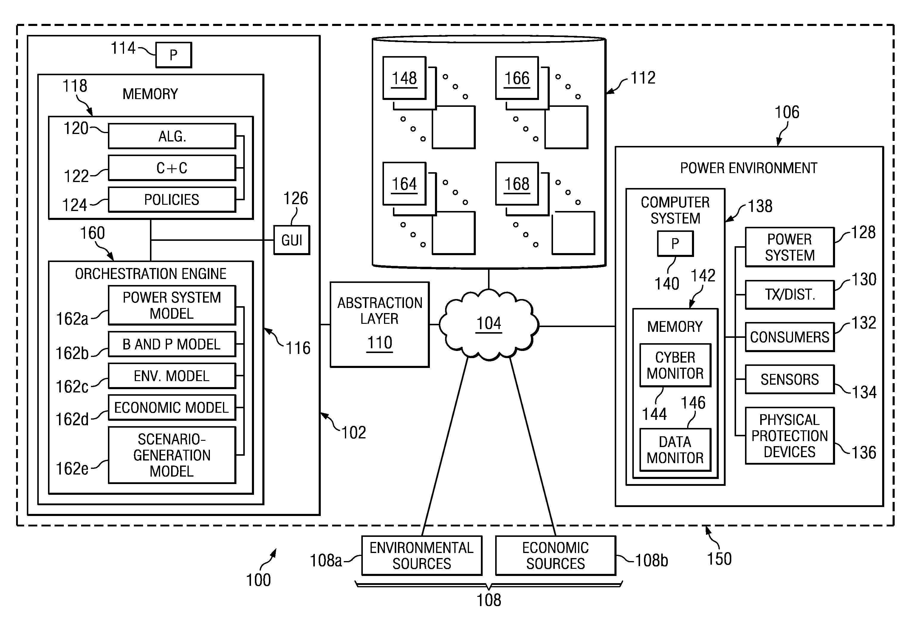
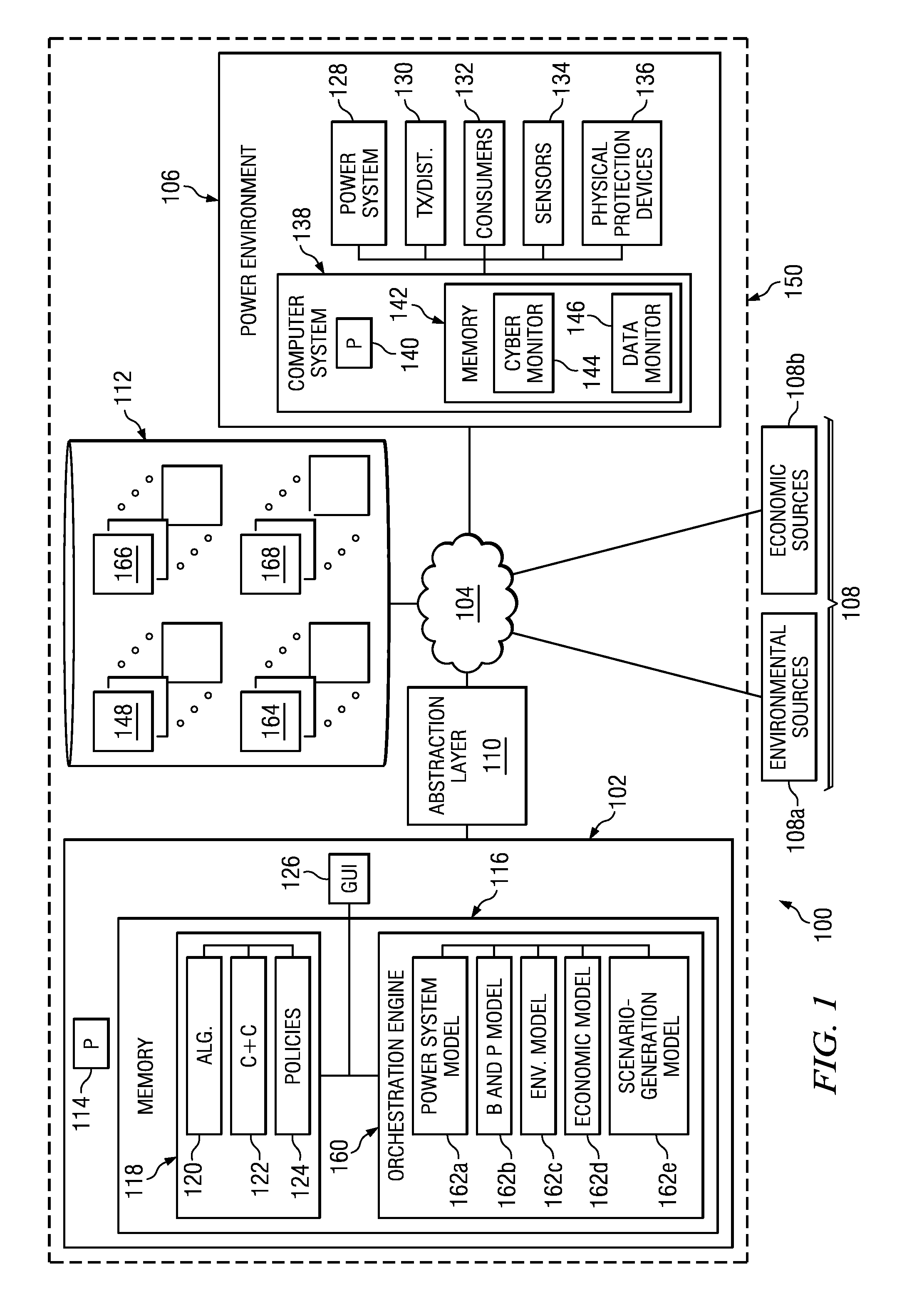
Electrical power is typically provided by an electrical power system that administers the generation of electrical power and how this power is delivered to consumers. The power system may include electrical power generation stations that generate electrical power using differing forms of energy. Examples of energy sources used by electrical power generation stations may include, but are not limited to, renewable and non-renewable energy sources. Particular examples may include hydro-dynamic power that harnesses the energy of moving water, solar power that harnesses solar radiant energy, wind power, and / or natural gas, coal, or other fossil fuel energy sources.

Each of these power generation systems may have characteristics that make their use advantageous in certain scenarios. For example, power generation systems that use renewable energy, such as wind energy, or solar energy may be desired based upon their ecologically friendly use of resources; however, these sources of energy may...


PUM


Abstract

In certain embodiments, a system includes one or more memory modules and one or more processing units. The one or more processing units access configuration parameters for configuring models that are operable to simulate operation of a power environment. A first subset of the models models power environment elements of the power environment. A second subset of the models models one or more external information sources, including an environmental source providing environmental data. The one or more processing units initiate configuration of the models according to the configuration parameters, resulting in configured models, and access operating parameters indicating operating conditions for the models to simulate. The one or more processing units initiate execution by the configured models of a simulation of the power environment according to the operating parameters. The configured models interact to execute the simulation. The simulation indicates how the simulated power environment behaves according to the operating parameters.

Description

BACKGROUNDElectrical power used by consumers, such as residential users, commercial users, government users, and industrial users, are typically provided by an electrical power grid. The electrical power grid generally includes multiple power generation stations that generate electrical power, and an electrical transmission / distribution system that delivers the generated electrical power to consumers.SUMMARYIn certain embodiments, a system includes one or more memory modules and one or more processing units. The one or more processing units access configuration parameters for configuring models that are operable to simulate operation of a power environment. A first subset of the models models power environment elements of the power environment. A second subset of the models models one or more external information sources, including an environmental source providing environmental data. The one or more processing units initiate configuration of the models according to the configuratio...

Claims


Application Information

Patent Timeline
Patent Type & Authority Applications(United States)
IPC IPC(8): G06F17/50
CPCH02J13/001H02J13/0086Y04S20/221Y02B70/3216Y04S10/40G06Q50/06H02J13/00001H02J13/00028Y02B70/30Y04S20/222Y02B70/3225H02J13/00006Y04S40/12Y02E60/00
Inventor GOEL, RIPAL S.WILLIAMSON, RON C.
Owner RAYTHEON CO
Why Eureka
Try Eureka