
High flow egr system

Active Publication Date: 2011-10-27
DEERE & CO
View PDF4 Cites 17 Cited by
  • Summary
  • Abstract
  • Description
  • Claims
  • Application Information

AI Technical Summary

Benefits of technology

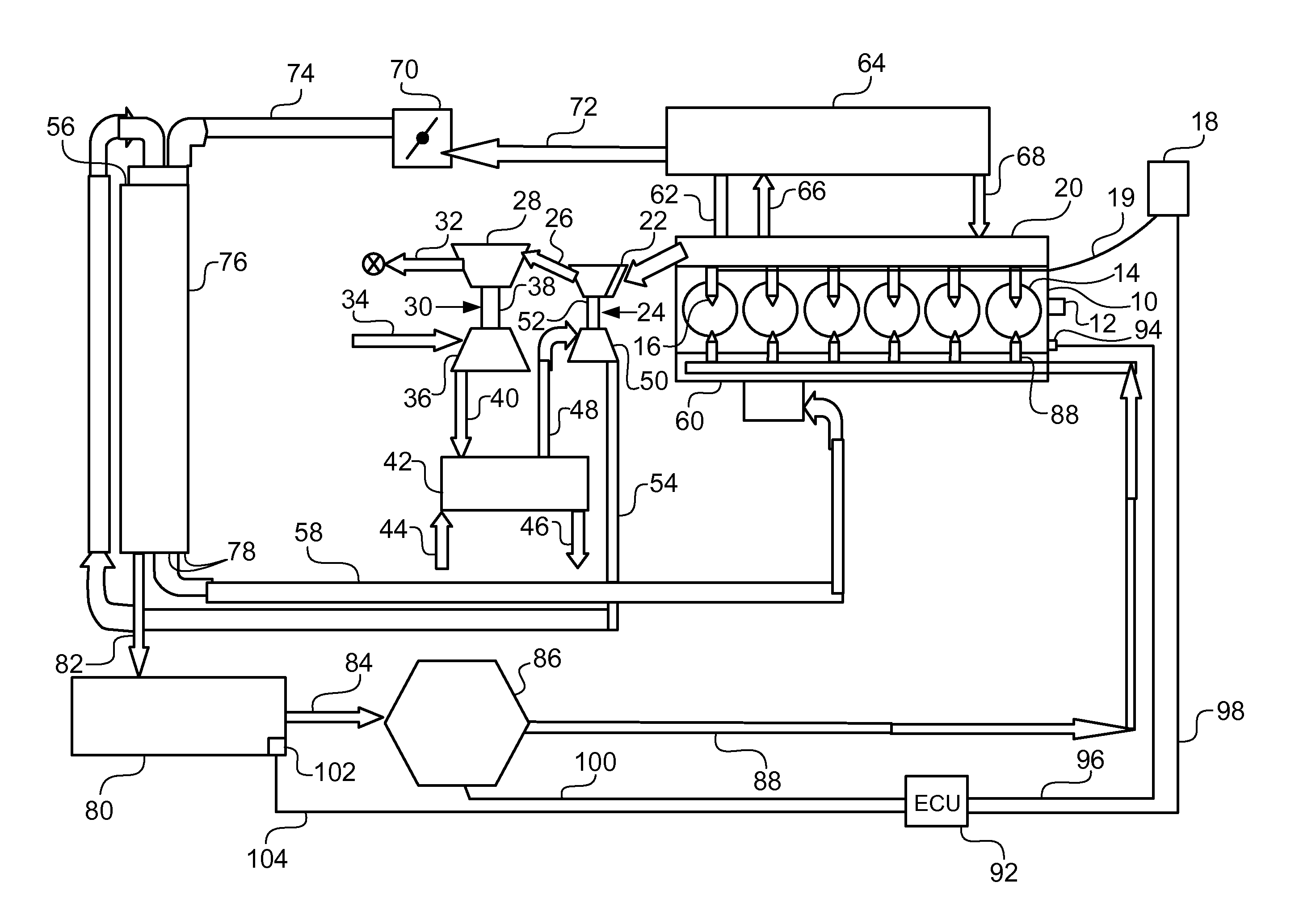
[0007]In one form, the invention is an EGR system for introducing significant percentages of exhaust gas into the intake of an air-breathing, fuel-consuming, multi-cylinder internal combustion engine having an exhaust for products of combustion and an intake for combustion air. This system includes a passage connecting the exhaust of the internal combustion engine to its intake and a valve for controlling flow of exhaust gasses through the passage. At least one heat exchanger is positioned in the passage for significant cooling of the gasses therein, thereby promoting condensation of moisture. A collector is positioned downstream of the heat exchanger for collection of condensed water from the gas stream. A liquid pump is fluidly connected to the collector and is, in turn, connected to a plurality of injectors adjacent the air intakes for the cylinders of the engine to permit uniform flow of liquid to the cylinders of the engine.

Problems solved by technology

One of the problems with a system of this type is that the moisture in the products of combustion reaches a point where the water condenses into droplets that can accumulate or puddle at random locations within the system.
While the engine can function with this occurrence, it can cause excess oxides of nitrogen in some cylinders and increased smoke and hydrocarbons in other cylinders.

Method used


Image

  • High flow egr system
  • High flow egr system

Examples


Embodiment Construction

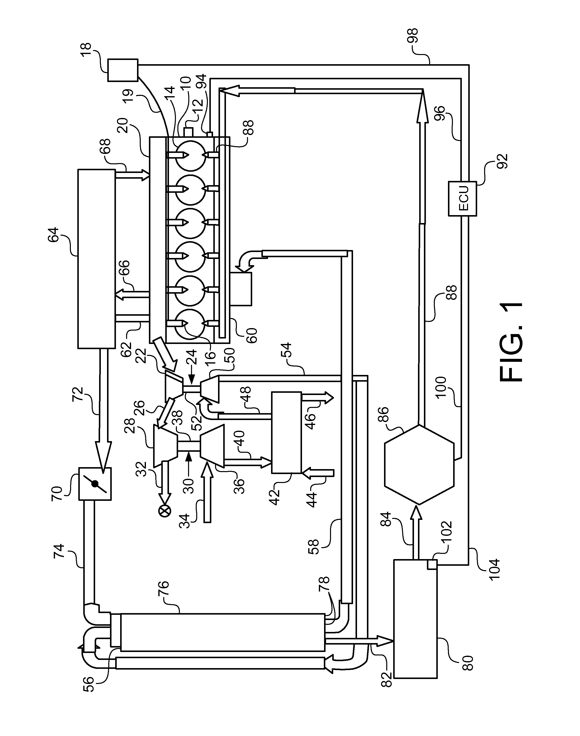
[0010]Referring to FIG. 1, there is shown in schematic fashion an internal combustion engine 10 providing a rotary power output through crankshaft 12. Engine 10 is a fuel-consuming, air-breathing, multi-cylinder internal combustion engine having a plurality of cylinders 14 in which individual pistons reciprocate and are connected to respective connecting rods providing a rotary power output through crankshaft 12. The cylinders 14, in the present instance, receive fuel through individual fuel injectors 16 for each cylinder from a fuel system 18 via a feed line 19. The fluid interconnections between the injectors 16 and the fuel system 18 are not shown in detail to simplify the description of the present invention. The system may be a high pressure common-rail in which high pressure in maintained in line 19 or a system in which high pressure is generated at the fuel injectors 16. Other fuel system types may be employed. When internal combustion engine 10 is of the compression ignition...


PUM


Abstract

A high flow EGR system for an internal combustion engine having a pair of series connected EGR coolers and a water droplet condensation collector and reservoir connected to the gas flow. The reservoir feeds a pump which is actuated to inject the liquid to the engine adjacent each cylinder for uniform distribution of the water to the engine cylinders. The pump is controlled to inject the water at appropriate conditions during the engine operating cycle.

Description

BACKGROUND OF THE INVENTION[0001]1. Field of the Invention[0002]The invention relates to exhaust gas recirculation (EGR) systems in which significant quantities of exhaust gas are recirculated to the intake of an internal combustion engine.[0003]2. Description of the Related Art[0004]In the continuing quest to meet lower emissions levels for internal combustion engines, the use of ever increasing quantities of EGR has been proposed. In order to reduce the combustion temperatures and, therefore, the generation of oxides of nitrogen, percentages of up to 50% and higher have been implemented. In order to minimize the effect of the large quantities of exhaust gas recirculation, it has become necessary to significantly cool the exhaust gasses to a point that greatly increases their density and minimizes the effect on power and fuel consumption when combined with the combustion air for the engine.[0005]One of the problems with a system of this type is that the moisture in the products of ...

Claims


Application Information

Patent Timeline
IPC IPC(8): F02M25/07
CPCY02T10/121F02B29/0412F02B29/0437Y02T10/146F02M25/074F02M25/028F02M25/0222F02M25/0732F02M26/24F02M26/35Y02T10/12
Inventor WINSOR, RICHARD E.PIPER, ERIK L.
Owner DEERE & CO
Learn More