Ball Valve Seats and Ball Valves Designed with Equilateral Triangle Section Methods

a triangle section and ball valve technology, applied in the field of ball valve seats, can solve the problems of no consideration, seal failure, seal failure, etc., and achieve the effects of low cost, simple design and convenient maintenan

Inactive Publication Date: 2011-10-27
XU CHANGXIANG +2
View PDF5 Cites 8 Cited by
  • Summary
  • Abstract
  • Description
  • Claims
  • Application Information

AI Technical Summary

Benefits of technology

[0046]c It is inevitable for the tight closure of a ball valve to be disturbed by its ball's wedging action, and its ball seat is an upset impulse amplifier with an inherent disturbance resistance index m; as shown in FIG. 5, the disturbance resistance index m [=Asp / (Ae+Ac)p=Ds2 / (Do2−Di2)] of the seat for floating ball valves determines their disturbance resistance for sealing services, where As=actuating areas of medium on balls (circular areas of dia.Ds), Ae=seat's annular areas exposed in cavity, Ac=seat's annular areas covered by balls (including non-contacting areas Aep), Ae+Ac=Au=annular actuating areas of medium on seats, p=medium pressure, Asp=ball-floated sealing forces or the ball-floated pressure or ball-floating forces from medium (thrust of medium on balls), (Ae+Ac)p=unsealing forces of medium on seats (thrust of medium on seats), Do=outside diameters of seats, Ds=actuating diameter of balls against seats, Di=inside diameter of seats; i.e. the greater the disturbance resistance factor m of their seat, the stronger the disturbance resistance of their sealing design; in other words, it should be to the maximum extent possible on the premise of not exceeding the material allowable strength to make the mounted seat for floating ball valves have a reduced actuating area (Ae+Ac) of medium on the seat, especially a reduced useless exposed area Ae thereof, so as to have a decreased amplified output of the ball wedged disturbance from eccentric drive and a more reliable closing seal.
[0069]It also needs to be further pointed out that the microline contact followed by a microsurface contact, or the microsawtooth ring contact, can effectively provide a seating stress necessary for sealing materials by the cutting line contact and also ensure them a safest allowable stress by the surface contact following the cutting line contact, which can increase the sealing performance and also decrease the preclamping force of seats to balls and reduce the operation torque, and is very suitably used to design the seals made of both high and low strength materials; for example, it can meet the needs of initial low pressure services by the line contact and then the needs of later high pressure services by the auto-deformed spherical surface contact to use a premade 90° conical surface but not a premade spherical surface as the ball sealing surface of seats, thus avoiding the useless crept deformation; however, only the ball valve seat designed according to equilateral triangles can ensure that it may have a ball clamping force so small as for the line contact to show its advantage. Therefore, it can be said that the section-designing method according to the equilateral triangle and the seal-designing method according to the microline contact followed by a microsurface contact are mutually supported and relied on in the designing of ball valve seats.

Problems solved by technology

The viscous behavior of the seat material under unenclosed compression surely causes the material to creep (causing a sealing stress relaxation) or to gradually deform and flow into extrusion gaps (causing a seal failure).
Therefore, the more the mass or the greater the size of the material used for a valve seat, the more the thermal deformation of the seat relative to the valve body and the more likely to cause a seal failure.
Heretofore, however, there have been no consideration of either using a ball valve seat of equilateral triangle sections or designing a ball valve seat or giving its dimensions by an equilateral triangle, and no further consideration of enclosing a ball valve seat for work as fully as possible.
US293057 and U.S. Pat. No. 4,385,747 prove that the prior art has often provided some axial vent grooves on the periphery of the seat ring to vent the fluid on the seat end face into the valve body cavity and to prevent the load on the upstream seat from being added on the ball and increasing the downstream seat load and the valve operation torque; however, at the moment the valve is fully opening, the horizontal portion of the seat will just face the ball bore and lose the spherical support of the ball, and the seat may be locally extruded into the ball bore and damaged if there is a flow through the seat end and the vent grooves; for this reason, the prior art can not help increasing the valve seat strength by enlarging its size or outside diameter or thickness and cause the valve seat to be more exposed.
In fact, a floating ball valve can not always maintain its tight closure by the ball floating force when W2≧Aep).
In other words, it is impractical to consider the tight closure of floating ball valves per self-sealing or to ensure that their W2 (ball clamping forces from seats) is not less than their Aep (actuation forces of medium on seat exposures in cavity), for such a consideration can not eliminate the inherent ball-wedged disturbance from eccentric drive and not ensure the reliability of the tight closure.
Since the prior art has been far away from the above-mentioned sealing science and can not make use of the ball-floating force Ws from medium but can not help relying on the bigger than Ws ball-clamping force W2 from seats to realize the tight closure of floating ball valves, all the floating ball valves of the prior art must be the formal floating ball valve whose on-off ball is clamped too tight by its two seats to float within the whole working pressure range.
The floating ball valve is characterized by simple design, low cost and easy maintenance, while the trunnion mounted ball valve, in contrast, by complex design, high cost and difficult maintenance.
The additional result is decreasing operation torque when using the trunnion mounted ball valve instead of the floating ball valve.

Method used


Image

  • Ball Valve Seats and Ball Valves Designed with Equilateral Triangle Section Methods
  • Ball Valve Seats and Ball Valves Designed with Equilateral Triangle Section Methods
  • Ball Valve Seats and Ball Valves Designed with Equilateral Triangle Section Methods

Examples


Embodiment Construction

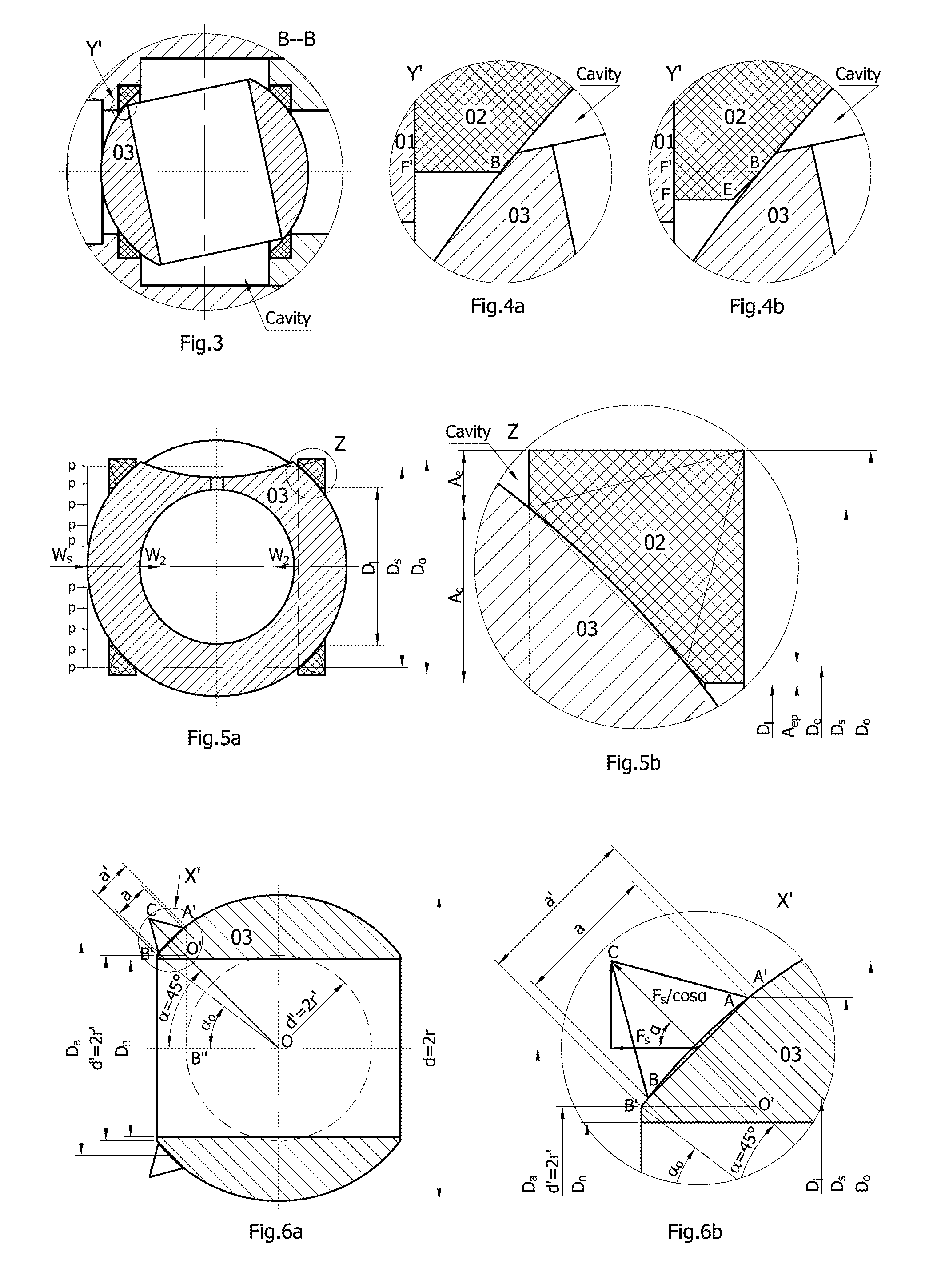
[0086]FIGS. 7a and 7b show a mounted seat 02 designed with an equilateral triangle ABC as its section factor, whose ball-sealing surface is formed by rotating arc AB opposite to side AB of the section-designing triangle ABC, whose supported cylindrical surface is formed by rotating the projection CD of side CA, and whose sealing end surface should have been formed by rotating the projection CF′ of side BC, but is actually the surface formed by rotating the intentionally extended projection CF of side BC to satisfy the special need of the upstream seat at the moment the valve is opening; the point F is the projection of the extension point E of side AB; if the side AB is not extended, the valve seat 02, as shown in FIG. 4a (the enlargement of the local view Y′ in FIG. 3), will have no extended segment BE as in FIG. 4b which can press the seat end tight on the valve body 01 by medium pressure thereon at the moment the valve is opening and may be pressed into the through hole of the ba...


PUM


Abstract

It is inevitable for the tight closure of a ball valve to be disturbed by its ball's wedging action, and its ball seat is an upset impulse amplifier with an inherent disturbance resistance index or a sealing maintaining factor m. The ball valve seat designed with equilateral triangle section methods of the invention can positively ensure itself a resistance to ball-wedged disturbance from eccentric drive to make a ball valve realize its tight closure by the floated pressure of balls or seats onto each other and ensure that the ultimate rotational resistance to the ball only relates to the ultimate pressure from / on one seat. Because the seat of the prior art can not ensure balls or seats against each other a floated pressure sufficient to resist to the ball-wedged disturbance from eccentric drive, the tight closure of the ball valve has to be realized by either larger preclamping force or larger spring preload between seats and balls so as for the ultimate rotational resistance to balls to be from larger ball-clamping forces from two seats. Therefore, the ball valve in accordance with the invention is a real floating or mounted ball valve, whose operation torque can be at most half of that of a formal or false floating ball valve of the prior art.

Description

TECHNICAL FIELD OF THE INVENTION[0001]The invention relates to ball valves used for fluid power and general use, more particularly to floating ball valves, trunnion-mounted ball valves and seat-mounted ball valves.TECHNICAL BACKGROUND OF THE INVENTION[0002]A ball valve is a kind of ball valves using a ball as the on-off member; the valve is fully open when turned to where the central through bore of the ball is coaxial with the valve passage, and fully closed when perpendicular to the valve passage. The prior art has had two types of ball valves, one floating ball valve and one trunnion-mounted ball valve. The invention, besides improving the designs of the two types of ball valves, proposes a seat-mounted ball valve. As we know, the floating ball valve is a kind of ball valves whose on-off ball is to float and whose seats is generally mounted under medium pressure for realizing the tight closure, whereas the trunnion-mounted ball valve is a kind of ball valves whose on-off ball is ...

Claims


Application Information

Patent Timeline
Patent Type & Authority Applications(United States)
IPC IPC(8): F16K5/06
CPCF16K5/204F16K5/0668
Inventor XU, CHANGXIANGXU, MAO YANGCHEN, ZHANJI
Owner XU CHANGXIANG
Why Eureka
Try Eureka