Apparatus and method for operating a spectrometer

a spectrometer and apparatus technology, applied in the field of apparatus and apparatus for operating a spectrometer, can solve the problems of large power consumption, system rate limitation, and inability to read integrator signals one at a time, and achieve the effect of reducing the cost of production, and increasing the cost of production

Inactive Publication Date: 2011-10-27
MOOG INSENSYS
View PDF2 Cites 3 Cited by
  • Summary
  • Abstract
  • Description
  • Claims
  • Application Information

AI Technical Summary

Benefits of technology

[0012]The invention extends to spectrometer apparatus configured to operate in accordance with the method of any preceding claim. The apparatus for reading a spectrometer may comprise a plurality of photosensitive diodes, at least one integrator and at least one analogue to digital converter. The photosensitive diodes may form the input to a switch matrix and the integrator(s) may be connected to the at least one analogue to digital converter to form the output of the switch matrix, such that at least some of the photosensitive diodes can be connected to the output of the switch matrix. Preferably, the switches of the switch matrix are field effect transistors.

Problems solved by technology

However, the analogue to digital converter can only read the integrator signals one at a time.
Therefore, the system is rate-limited by the speed with which the analogue to digital converter is able to process the signals from the integrators.
However, the system is expensive to manufacture and requires large amounts of power to operate.

Method used


Image

  • Apparatus and method for operating a spectrometer
  • Apparatus and method for operating a spectrometer
  • Apparatus and method for operating a spectrometer

Examples


Embodiment Construction

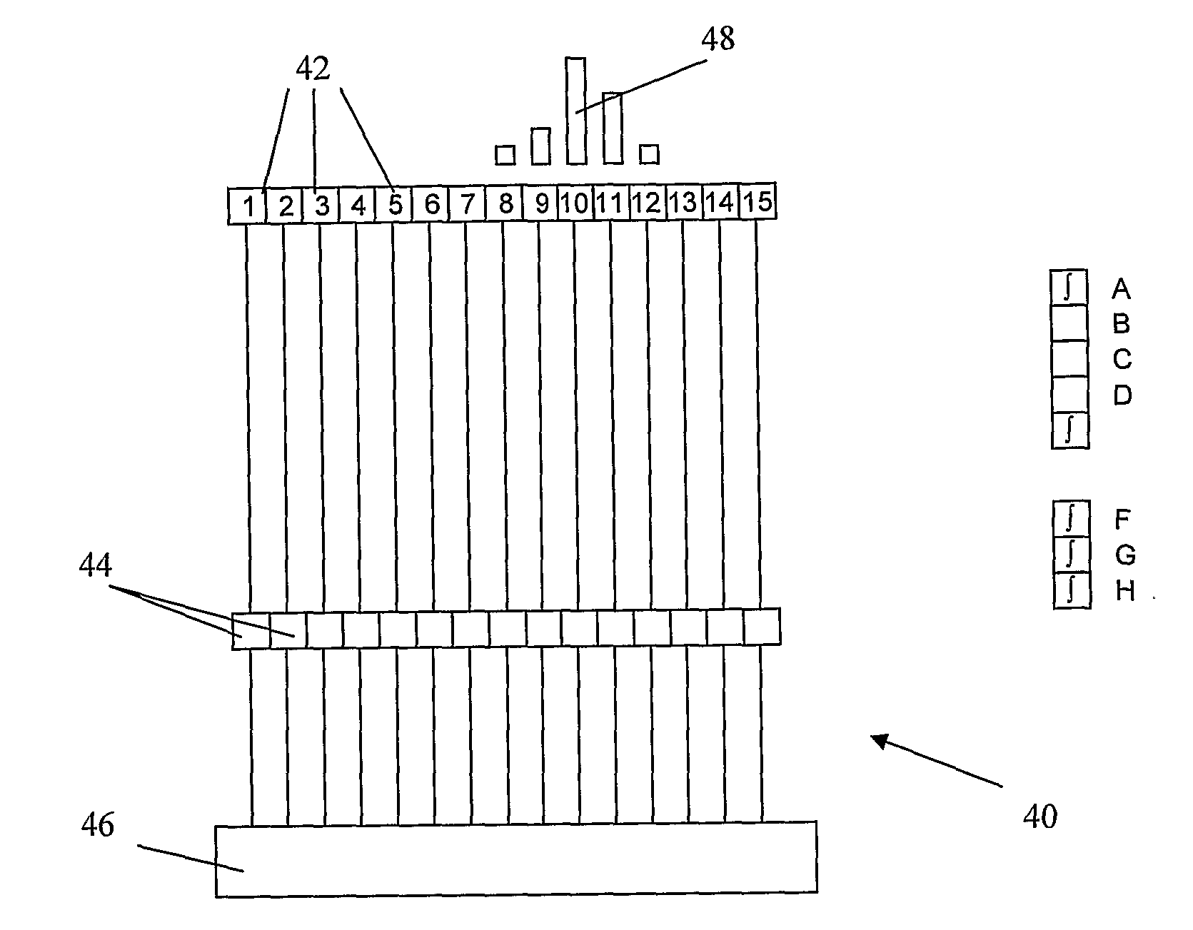
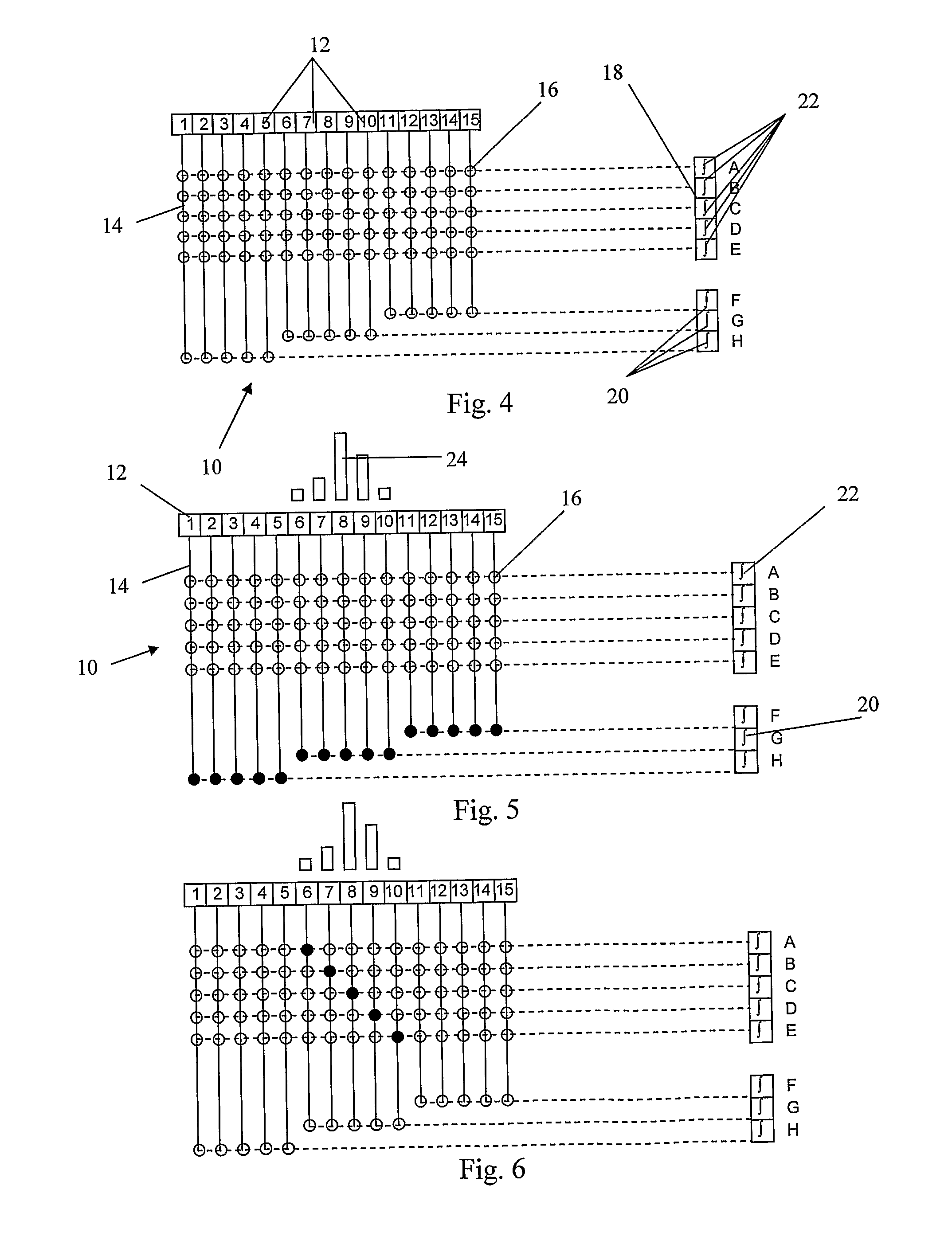
[0022]FIG. 4 shows spectrometer reading apparatus 10 comprising a plurality of photosensitive diodes, or pixels, 12 connected as inputs to a switch matrix 14. The switches of the switch matrix 16 comprise field effect transistors. Integrators 18 are connected to the output of the matrix 14. The integrators 18 comprise group integrators 20 and individual integrators 22. The group integrators 20 are each connected to adjacent groups of five pixels 12. As shown in FIG. 4, several pixels 12 are routed to one group integrator 20 by closing multiple switches in the matrix 16. This sums the currents from each of the pixels 12 and routes them to a common group integrator 20. The individual integrators 22 are connected to the switch matrix 16 such that any pixel 12 maybe put in communication with any of the individual integrators 22. The switch matrix 14 is a non-blocking matrix with respect to the pixels 12 and the individual integrators 22.

[0023]The individual integrators 22 are connected ...


PUM


Abstract

A method of operating a spectrometer to determine the wavelength of an optical signal, in particular for determining the resonant wavelength of an optical fibre Bragg grating. The spectrometer comprises an array of photosensitive pixels each of which generates an output signal in response to the intensity of light incident on the pixel, and a refractive element arranged to direct light to a particular position in the array depending on the wavelength of the light. The method involves selecting a first group of pixels in the array by reference to an expected wavelength distribution of the optical signal and monitoring the output signals from the first group of pixels. On the basis of the output signals from the first group of pixels a second group of pixels is selected and the wavelength of the optical signal is determined from the output signals of the second group of pixels. The method has the advantage that the wavelength of the optical signal can be determined without scanning every pixel in the array individually.

Description

FIELD OF THE INVENTION[0001]This invention relates to apparatus and a method for operating a spectrometer to determine the wavelength of an optical signal, in particular for determining the resonant wavelength of an optical fibre Bragg grating.BACKGROUND TO THE INVENTION[0002]A typical spectrometer comprises an array of photosensitive pixels (photodiodes) each of which generates an output signal in response to the intensity of light incident on the pixel, and a refractive element arranged to direct light to a particular position in the array depending on the wavelength of the light.[0003]Various known readout configurations are shown in FIGS. 1 to 3. FIG. 1 shows a plurality of photosensitive diodes each connected to a common integrator via a multiplexer. The integrator is connected to a common analogue to digital converter. During operation, each photosensitive diode, or pixel, is captured and read out in turn. This system captures and reads each pixel in turn and therefore takes a...

Claims


Application Information

Patent Timeline
Patent Type & Authority Applications(United States)
IPC IPC(8): G01J3/46
CPCG01J3/1895G01J9/00G01J3/2803
Inventor VOLANTHEN, MARKLLOYD, GLYNN
Owner MOOG INSENSYS
Why Eureka
Try Eureka