Laser Scanner

a laser scanner and scanner technology, applied in the field of laser scanners, can solve the problems of high cost of laser scanners, and large amount of work operations, and achieve the effect of increasing the measurement density

Active Publication Date: 2011-10-27
KK TOPCON
View PDF6 Cites 9 Cited by
  • Summary
  • Abstract
  • Description
  • Claims
  • Application Information

AI Technical Summary

Benefits of technology

[0018]Also, the invention provides the laser scanner as described above, wherein the optical system has an optical path deflecting means for deflecting optical path of the pulsed beams. As a result, it is possible to heighten the measurement density.

Problems solved by technology

In this case, a plurality of costly line scanners are needed, and much time and more working operations have been needed for the adjustment of the acquired data.
Accordingly, the laser scanner is costly.

Method used


Image

  • Laser Scanner
  • Laser Scanner
  • Laser Scanner

Examples


Embodiment Construction

[0029]Description will be given below on embodiments of the present invention by referring to the attached drawings.

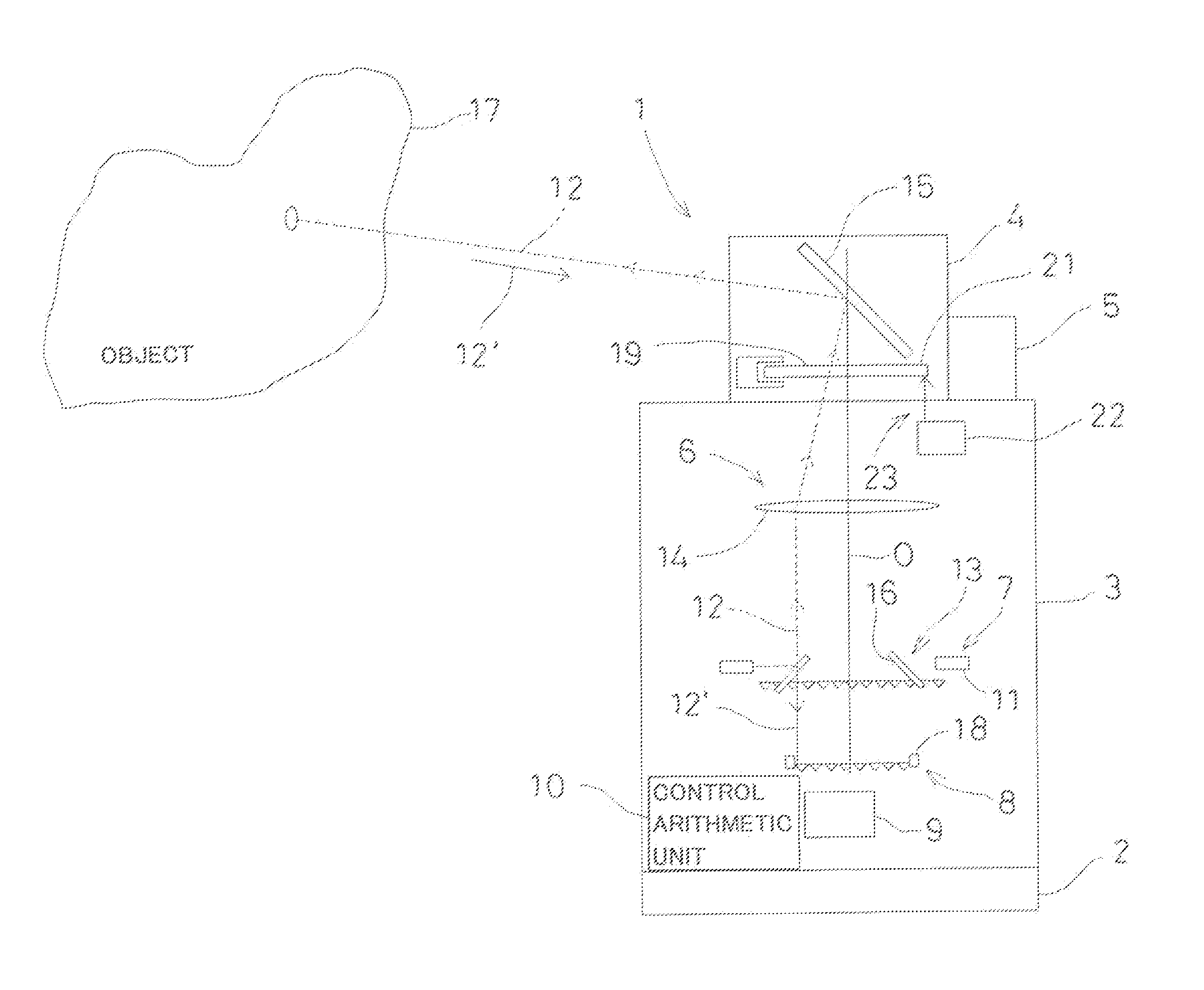
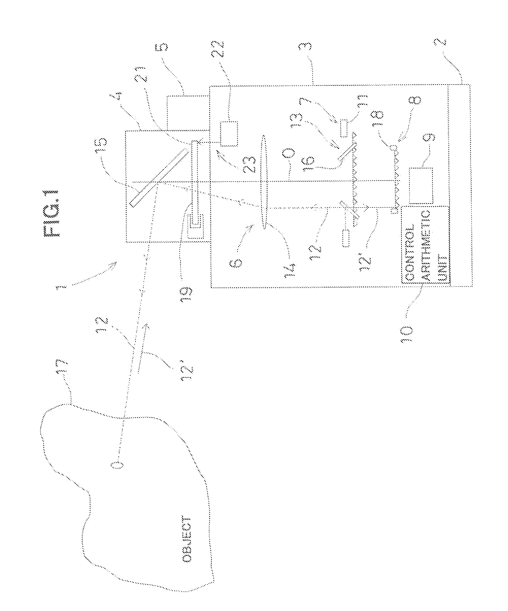
[0030]First, referring to FIG. 1, description will be given on general features of a laser scanner according to the present invention.

[0031]A laser scanner 1 comprises a leveling unit 2, a main unit 3, and a rotating unit 4.

[0032]The main unit 3 is installed via the leveling unit 2, and the leveling unit 2 has a function to adjust posture of the main unit 3 by taking a horizontal direction as reference.

[0033]The rotating unit 4 is rotatably mounted around a vertical axis (a centerline of rotation) with respect to the main unit 3, and the rotating unit 4 is designed to be rotated at a constant speed by a rotary driving unit 5.

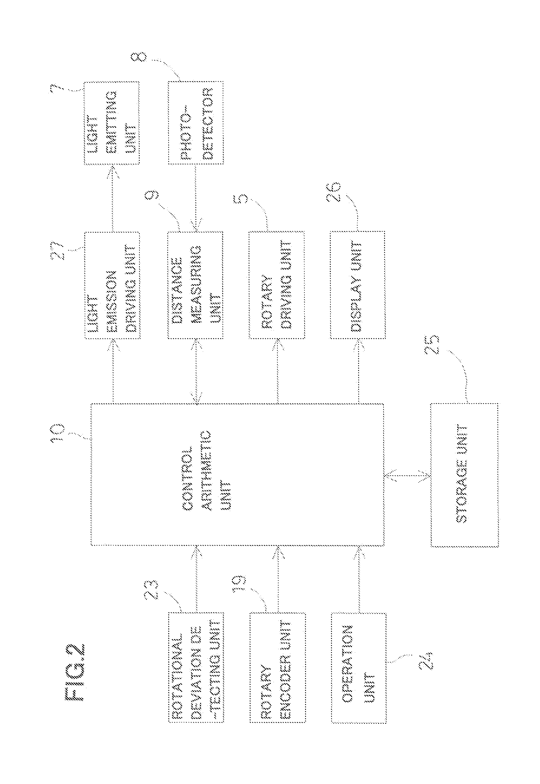
[0034]The main unit 3 comprises a light-projecting and light-receiving optical system 6, a light emitting unit 7, a photodetector 8, a distance measuring unit 9, and a control arithmetic unit 10. An optical axis O of the light-projecting and light-...


PUM


Abstract

The invention provides a laser scanner 1 for performing multi-point measurement by projecting a pulsed beam 12 over total circumference for scanning, comprising a main unit 3 and a rotating unit 4 rotatably mounted on the main unit, wherein the rotating unit has a deflection member 15 for projecting the pulsed beams by deflecting the beams perpendicularly to center axis of the rotating unit, the main unit comprises a plurality of light emitting sources 11 disposed in two-dimensional positions and used for emitting a plurality of pulsed beams, an optical system 6 for projecting and receiving the pulsed beams, a rotation angle detecting unit 19 for detecting a horizontal rotation angle of the rotating unit, a plurality of photodetectors 8 for receiving a reflection light 12′ from an object via the deflection member and being disposed respectively at positions conjugate to the light emitting sources, a distance measuring unit 9 for measuring a distance based on a photodetection signal from the photodetector, and a control arithmetic unit 10 for calculating projecting directions of the pulsed laser beams projected from the deflection member based on the disposed position of the light emitting sources and on the result of detection by the rotation angle detecting unit.

Description

BACKGROUND OF THE INVENTION[0001]The present invention relates to a laser scanner for projecting pulsed laser beams to scan over total circumference, for measuring a multiple number of points at high speed and for acquiring three-dimensional position data at the multiple number of points.[0002]In the past, a line scanner has been known as a laser scanner, which projects a single pulsed laser beam on a straight line for scanning and acquires distance measurement data for each pulse.[0003]In recent years, there have been increasing demands to acquire data at higher speed over total circumferential direction of 360°. In case it is necessary to acquire the data over total circumferential direction, a plurality of line scanners are used to acquire the data. In this case, a plurality of costly line scanners are needed, and much time and more working operations have been needed for the adjustment of the acquired data.[0004]As a device for acquiring data at a multiple number of points in to...

Claims


Application Information

Patent Timeline
Patent Type & Authority Applications(United States)
IPC IPC(8): G01B11/24G01S17/89
CPCG01S7/4812G01S7/4817G02B26/105G01S17/89G02B26/0816G01S17/42
Inventor OHTOMO, FUMIOKUMAGAI, KAORUCHIBA, MINORU
Owner KK TOPCON
Why Eureka
Try Eureka