Image forming apparatus and image forming method
a technology of image forming apparatus and forming method, which is applied in the direction of electrographic process apparatus, instruments, optics, etc., can solve the problem of more tails liable to occur, and achieve the effect of preventing the scattering of toner
- Summary
- Abstract
- Description
- Claims
- Application Information
AI Technical Summary
Benefits of technology
Problems solved by technology
Method used
Image

Examples
embodiment 1
[0033]First, the first embodiment of the invention will be described with reference to FIGS. 1 to 4 and 7.
[0034]FIG. 7 is a vertical side sectional view illustrating a schematic construction of a laser beam printer (LBP) as an image forming apparatus according to the invention.
[0035]A photosensitive drum 1202 (image bearing member) is uniformly charged by a charging roller 1213 (charging unit). After that, based on an image signal (also referred to as image information) included in data of a print job transmitted from a host computer (not shown), a scanner 1201 (exposing unit) modulates an intensity of a laser beam, thereby forming an electrostatic latent image onto the photosensitive drum 1202 (onto the image bearing member). Toner is deposited onto the electrostatic latent image on the photosensitive drum 1202 by a developing roller 1214 (developing unit), thereby forming a toner (developer) image (visible image).
[0036]Transfer materials in an enclosing cassette 1203 are picked up...
embodiment 2
[0084]Subsequently, the second embodiment of the invention will be described with reference to FIGS. 5 and 6.
[0085]Since a whole construction (FIG. 7) and functions of an image forming apparatus in the embodiment are similar to those in the first embodiment, their description is omitted and points different from the first embodiment will be described.
[0086]In the defective images such as tail and offset, the level changes due to some factors besides the kind of transfer material. One of the factors is the foregoing toner amount. There is a plurality of parameters regarding the toner amount. As typical parameters, there are a charging bias and a developing bias. The charging bias or developing bias is applied as a predetermined value (refer to FIG. 5) to the charging roller 1213 or developing roller 1214 by a high voltage power source apparatus (not shown). The applied bias becomes a bias of the charging roller 1213 or developing roller 1214. There is a case where in order to properl...
embodiment 3
[0095]In the embodiment, as a method of changing the thin-out process according to the various conditions, the laser power has been made variable and the exposure light amount has been changed.
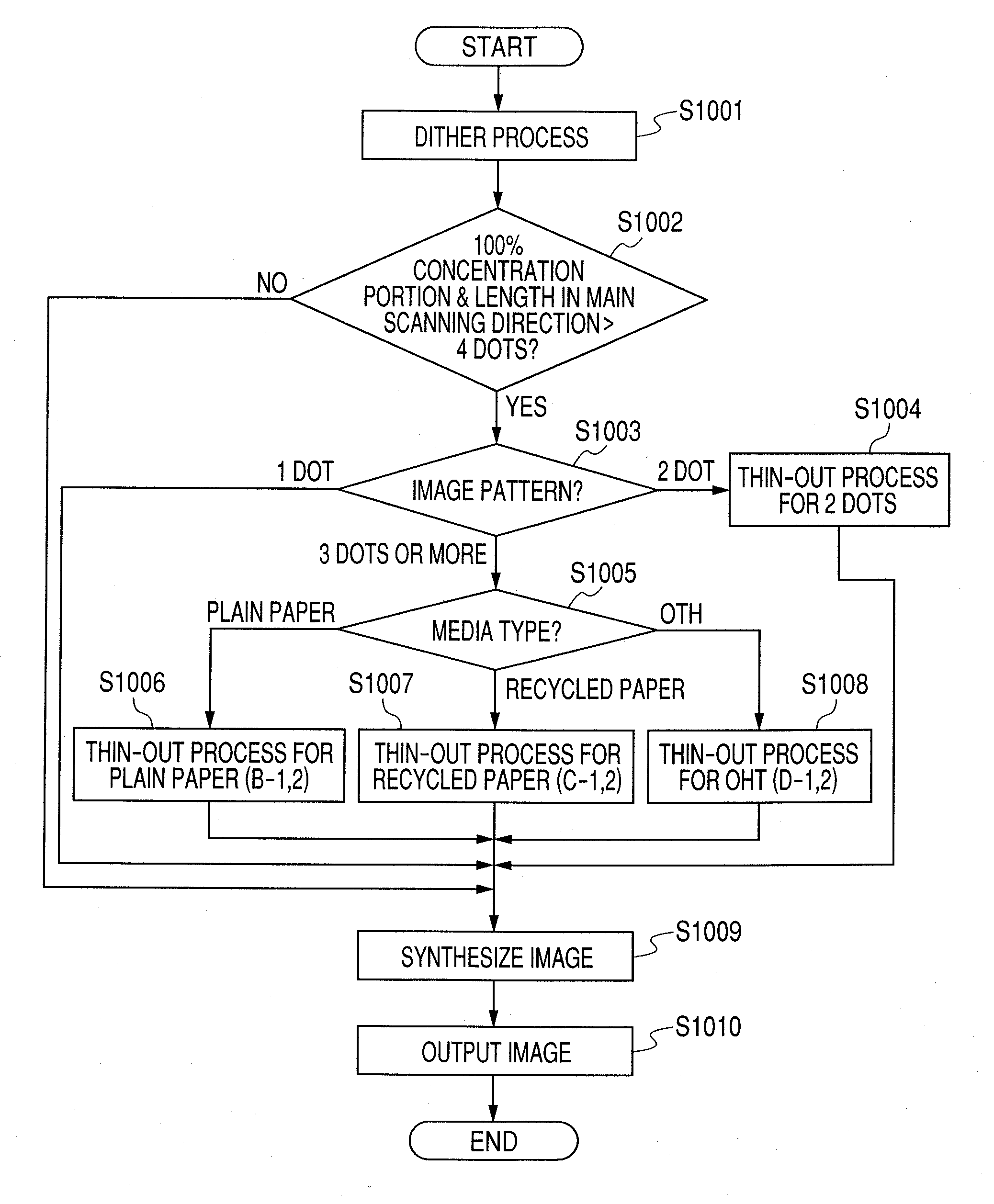
[0096]In the embodiment 1, the thin-out area has been made variable according to the transfer material kind. In the embodiment 2, the laser pulse width (laser light emission time) in the thin-out area has been made variable according to the charging condition, developing condition, and environment condition. According to the methods of the thin-out process as mentioned in the embodiments 1 and 2, since it is necessary to extract, modify, and synthesize the image data, there is a fear that the image processes become complicated and a print speed decreases.
[0097]In the embodiment, therefore, the thin-out process is changed by making the laser power variable without executing the image processes as described in the embodiments 1 and 2. More specifically speaking, in steps S1006, S1007, and S1008 ...
PUM
 Abstract
Description
Claims
Application Information