
Cable and/or rod control system for a gearbox on a heavy goods vehicle with tilting cab

a technology of cab and control system, which is applied in the direction of shafts, mechanical control devices, manual control with single control members, etc., can solve problems such as control system malfunction, and achieve the effect of simple structure and easy mounting

Inactive Publication Date: 2011-11-03
SOC EURO DE FAB IND SEFI
View PDF13 Cites 3 Cited by
  • Summary
  • Abstract
  • Description
  • Claims
  • Application Information

AI Technical Summary

Benefits of technology

[0006]This invention aims to overcome these disadvantages, and it preferably aims to provide a control system for a gearbox on a heavy goods vehicle that has a simple structure, which does not require a significant length of cable or rod, whilst allowing the control system to be mounted easily on the heavy goods vehicle.
[0011]Mounting a first assembly on the cab of the heavy goods vehicle and a second assembly on the chassis of the heavy goods vehicle designed to cooperate with each other in the operating position of the cab makes it possible for the control means to avoid passing through the articulation of the cab and therefore to limit the length of the latter.
[0012]In addition, this control system structure enables the control system to be easily mounted on the heavy goods vehicle, since the two assemblies can be mounted separately, respectively, on the cab and the chassis, before these are assembled.
[0017]According to another aspect of the invention, the two actuation levers are mounted such that they pivot around a coincident axis. These arrangements enable the wear between the contact portions of the two control levers to be limited.
[0024]According to one characteristic of the invention, the units belonging to the first and second assemblies comprise means for positioning and locking the units in the operating position of the cab. These arrangements avoid a gap between the units in the operating position of the cab, which could cause poor cooperation of the control levers and therefore a control system malfunction.

Problems solved by technology

The alternate flexing of the cable can cause the cable to wear, which may lead to control system malfunctions.

Method used


Image

  • Cable and/or rod control system for a gearbox on a heavy goods vehicle with tilting cab
  • Cable and/or rod control system for a gearbox on a heavy goods vehicle with tilting cab
  • Cable and/or rod control system for a gearbox on a heavy goods vehicle with tilting cab

Examples


Embodiment Construction

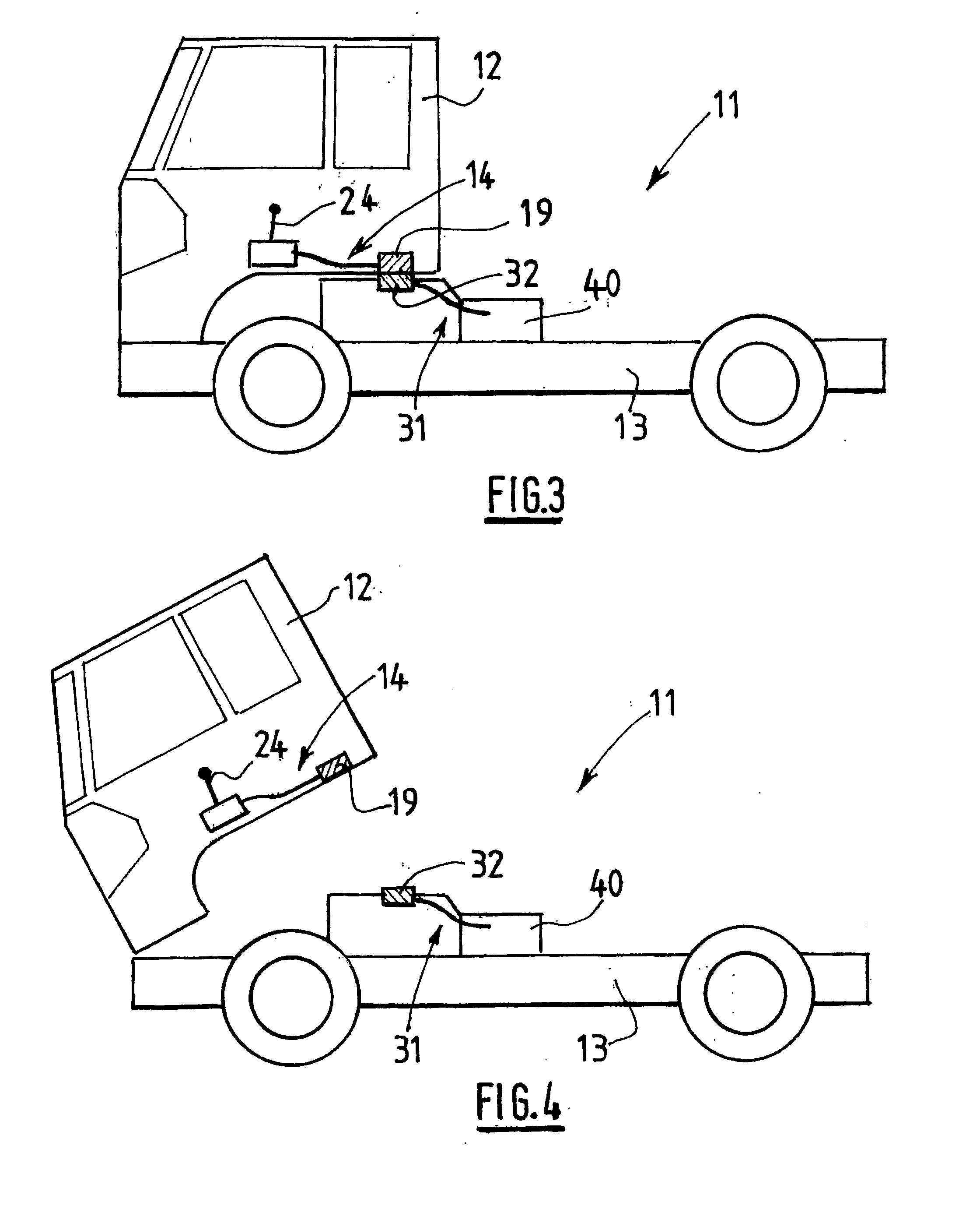
[0036]FIGS. 3 and 4 represent a heavy goods vehicle 11 with a tilting cab equipped with a cable control system for a gearbox. The cab 12 of the heavy goods vehicle is mobile between an operating position (represented in FIG. 3) in which it rests on the chassis 13 of the heavy goods vehicle 11 and a tilted position (represented in FIG. 4).

[0037]The control system comprises a first assembly 14 mounted on the cab 12 of the heavy goods vehicle 11.

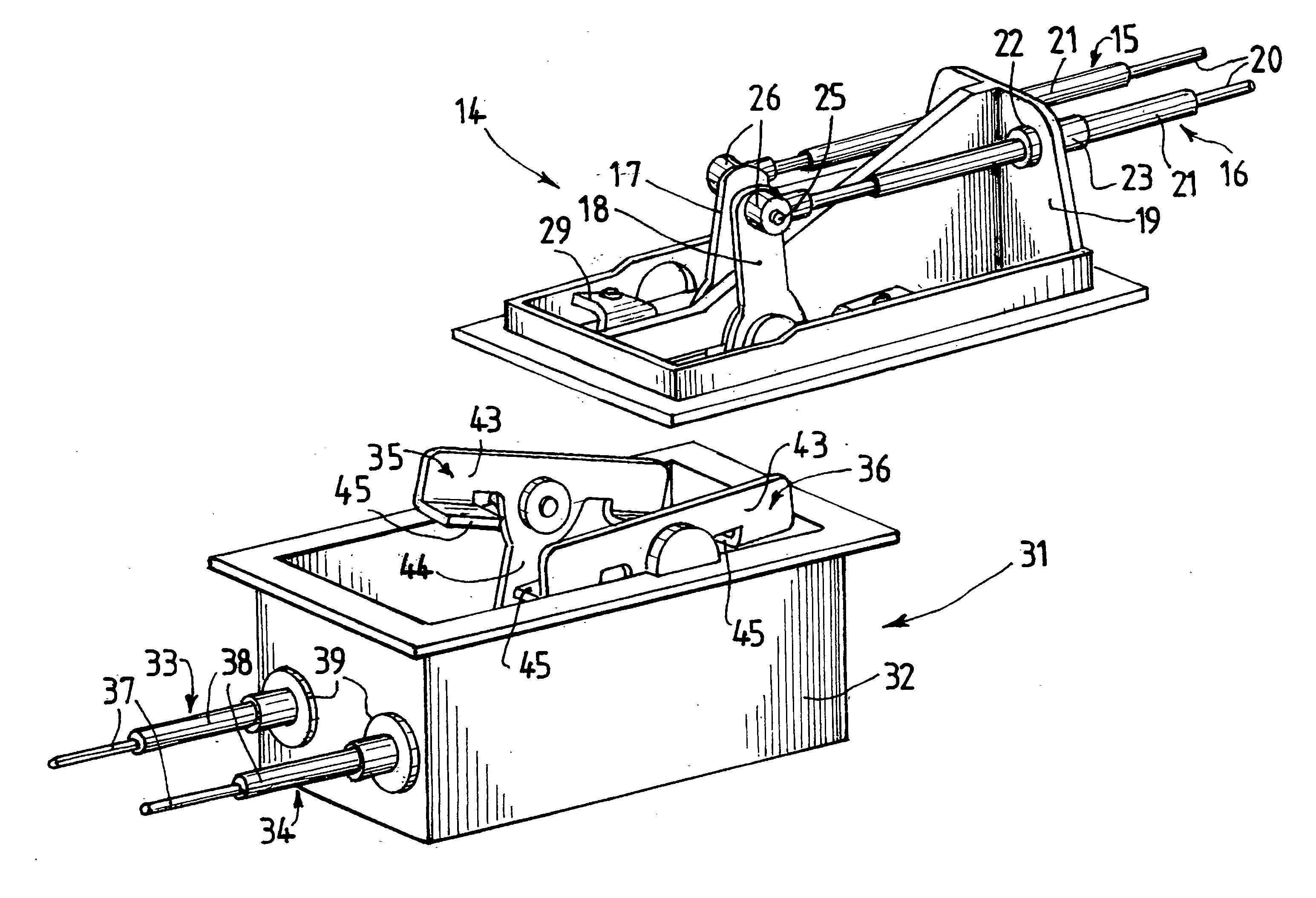
[0038]As shown more specifically in FIG. 5, the first assembly 14 comprises an open unit 19 mounted on the cab 12, the opening of the unit 19 being located on the side of the chassis 13 of the heavy goods vehicle 11 in the operating position of the cab 12.

[0039]As shown more specifically in FIGS. 5 and 6, the first assembly 14 also comprises a gear selection cable 15 and a gear shift cable 16, as well as a gear selection lever 17 and a gear shift lever 18. The gear selection lever 17 and the gear shift lever 18 are housed in the unit 19 and are...


PUM


Abstract

The invention relates to a control system, comprising—a first assembly (14), fitted to the cabin (12) of the heavy goods vehicle (11) with at least one control cable, one end of which is designed to be fitted to a gear lever (24) of the heavy goods vehicle, the other end being connected to a operating means such as to move the operating means between first and second positions on a movement of the gear lever (24) by a user, a second assembly (31) mounted on the chassis (13) of the heavy goods vehicle (11) and comprising at least one control cable, one end of which is connected to an operating means and the other end of which is designed to be connected to a gearbox (40) of the heavy goods vehicle such as to bring about a change of gear ratio on a movement of the operating means between the first and second positions, the two operating means cooperating with each other in the operating position of the cabin such that a movement of the operating means of the first assembly (14) brings about a movement of the operating means of the second assembly (31).

Description

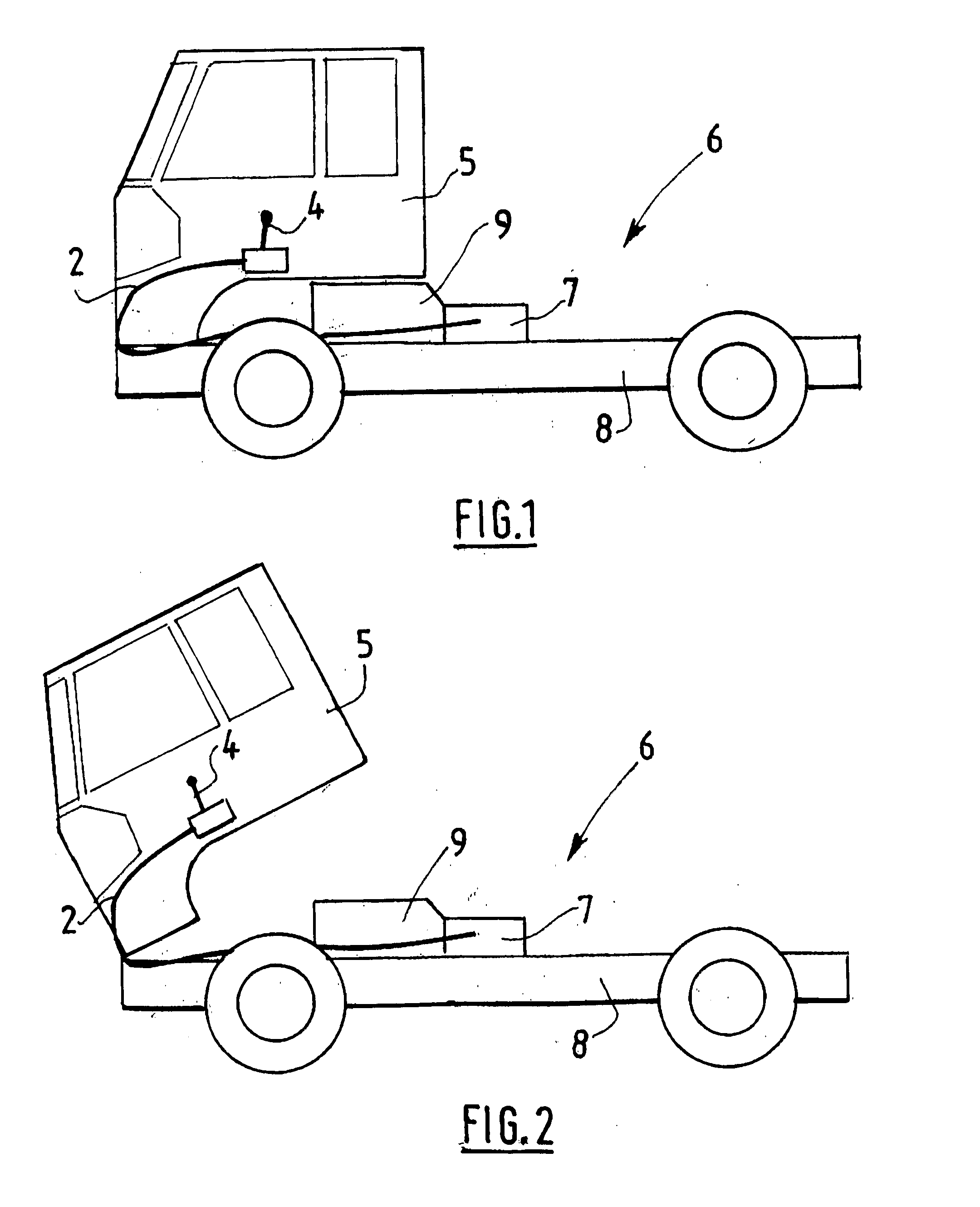
TECHNICAL FIELD[0001]This invention concerns a cable and / or rod control system for a gearbox on a heavy goods vehicle with a tilting cab.BACKGROUND[0002]As shown in FIGS. 1 and 2, such a control system comprises, in a known manner, a control cable 2, one end of which is connected to a gear lever 4, housed in the cab 5 of a heavy goods vehicle 6 and the other end of which is connected to a gearbox 7, mounted on the chassis 8 of the heavy goods vehicle and equipped to adapt the engine torque and the rotation direction of the engine 9 of the heavy goods vehicle.[0003]In view of the fact that the cab 5 is mobile between an operating position in which it rests on the chassis 8 of the heavy goods vehicle (represented in FIG. 1) and a tilted position (represented in FIG. 2), it is necessary to pass the control cable 2 at the level of the articulation of the cab 5 in order to avoid risks related to the presence of a taut cable between the cab and the chassis in the tilted position of the ca...

Claims


Application Information

Patent Timeline
IPC IPC(8): F16H63/30
CPCB62D33/073F16C1/101Y10T74/20018Y10T74/20049F16H61/26F16C2361/65
Inventor FERRON, MICHEL
Owner SOC EURO DE FAB IND SEFI
Learn More