Valve System

a valve system and valve body technology, applied in the direction of valve arrangements, non-mechanical valves, machines/engines, etc., can solve the problems of increased and unnecessary driving torque, fuel economy and component durability may be compromised, and the noise and wear of the valve body can be reduced. , to achieve the effect of reducing noise and wear

Inactive Publication Date: 2011-11-03
FORD GLOBAL TECH LLC
View PDF5 Cites 8 Cited by
  • Summary
  • Abstract
  • Description
  • Claims
  • Application Information

AI Technical Summary

Benefits of technology

[0002]Cylinder intake and exhaust events of internal combustion engines may be controlled via poppet valves positioned within the intake and exhaust ports of a cylinder. These poppet valves can be opened by mechanical force provided by cam lobes of a camshaft. The valves close when the valves, or extensions from the valves (e.g., a tappet), encounter a base circle portion of the camshaft. A

Problems solved by technology

Increasing spring forces to counteract cylinder port pressures can lead to additional problems, however.
These higher spring forces may cause increased and unnecessary driving torques during normal, lower RPM operating

Method used


Image

  • Valve System
  • Valve System
  • Valve System

Examples


Embodiment Construction

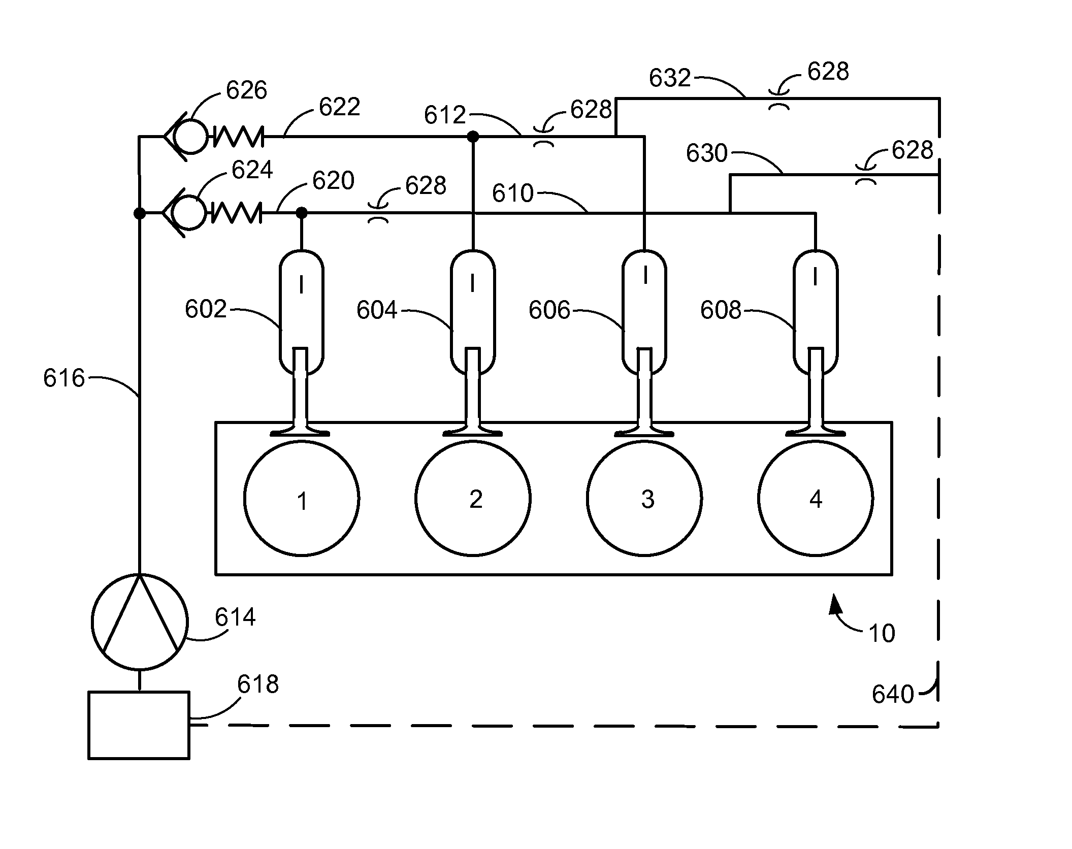
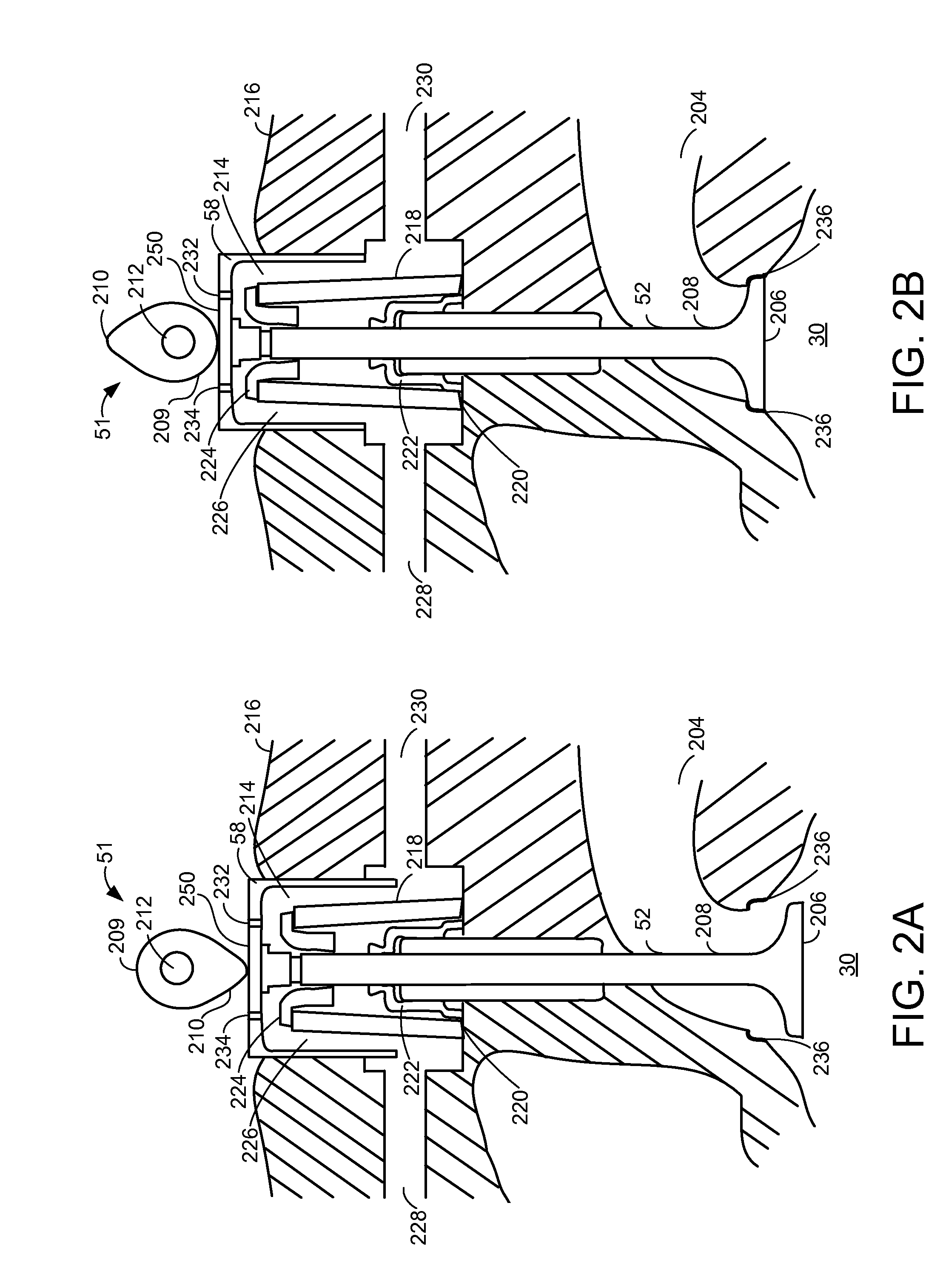
[0015]The present description relates to systems and methods for operating a valve system of an internal combustion engine. In one non-limiting example, the engine may be configured as illustrated in FIG. 1. Further, various examples of the valve system as illustrated in FIGS. 2A-B and 5-8 may be part of the engine of FIG. 1.

[0016]Valve closing forces may be provided according to the system depicted in FIGS. 3A-B and the method illustrated in FIG. 9, which shows an example method for providing valve closing force. FIG. 4 illustrates signals of interest during engine operation according the method of FIG. 9.

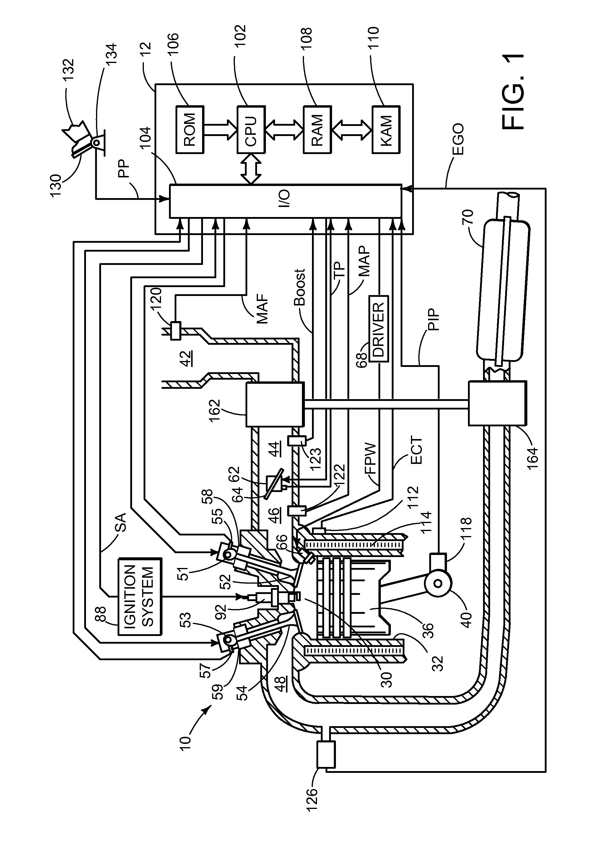
[0017]FIG. 1 is a schematic diagram showing one cylinder of multi-cylinder engine 10, which may be included in a propulsion system of an automobile. Engine 10 may be controlled at least partially by a control system including controller 12 and by input from a vehicle operator 132 via an input device 130. In this example, input device 130 includes an accelerator pedal and a pedal p...


PUM


Abstract

A valve system for providing closing force to one or more valves of an engine is provided. In one example, the system comprises a first tappet bore in fluid communication with a second tappet bore via a bidirectional oil passage. The system may provide valve closing forces to assist in the closing of valves coupled to the tappet bores, lowering required valve spring forces.

Description

FIELD[0001]The present description relates to controlling valve opening and closing.BACKGROUND AND SUMMARY[0002]Cylinder intake and exhaust events of internal combustion engines may be controlled via poppet valves positioned within the intake and exhaust ports of a cylinder. These poppet valves can be opened by mechanical force provided by cam lobes of a camshaft. The valves close when the valves, or extensions from the valves (e.g., a tappet), encounter a base circle portion of the camshaft. A valve may close due to spring force from a valve spring coupled to the valve stem. Hydraulic dampening mechanisms are often present to reduce noise and wear to the valvetrain components due to higher valve closing forces. Such dampening mechanisms can include an oil-filled chamber housing the valve stem to provide pressure against the closing force of the valve and to softly seat the valve.[0003]The inventor herein has recognized a number of issues with the above approach. The required static...

Claims


Application Information

Patent Timeline
IPC IPC(8): F01L9/02F01L9/12
CPCF01L1/14F01L9/023F01L1/462F01L9/12
Inventor FABROS, CHARLES
Owner FORD GLOBAL TECH LLC
Why Eureka
Try Eureka