Isolater for fuel injector

a fuel injector and isolation device technology, applied in the direction of noise reduction fuel injection, fuel injection apparatus, charge feed system, etc., can solve the problems of affecting the placement of highly precise fuel spray pattern into the combustion chamber, affecting the placement of highly precise fuel spray pattern, and affecting the placement of the injector tip plugging

Inactive Publication Date: 2011-11-03
DELPHI TECH INC
View PDF31 Cites 16 Cited by
  • Summary
  • Abstract
  • Description
  • Claims
  • Application Information

AI Technical Summary

Benefits of technology

[0008]A fuel injector-engine component assembly for an internal combustion engine is provided. The fuel injector-engine component assembly includes an engine component with a stepped bore defined along an axis. The stepped bore includes a stepped bore stop surface facing axially upward. A fuel injector is disposed in the stepped bore and extends along the axis. The fuel injector includes a fuel injector stop surface facing axially downward and axially opposing the stepped bore stop surface to define a predetermined annular space. In operation, the fuel injector is subjected to axial pulses that tend to drive the fuel injector stop surface and the stepped bore stop surface together. An isolation ring is disposed in the predetermined annular space and axially between the stepped bore stop surface and the fuel injector stop surface for axially isolating the fuel injector from the engine component. The isolation ring includes a rigid support member for limiting the axial motion of the stepped bore stop surface and the fuel injector stop surface together to a predetermined, limited degree. The isolation ring also includes a resilient and compliant isolation member located axially between the stepped bore stop surface and the fuel injector stop surface. The isolation member has sufficient resilience, compressibility, and insulative potential to provide at least one of acoustic and thermal isolation between the fuel injector and the cylinder head below a predetermined pressure of the fuel injector.

Problems solved by technology

However, direct metal-to-metal contact between the bottom surface of the direct injection fuel injector body and the top surface of the shoulder allows for unmitigated transfer of the vibration from the direct injection fuel injector to the cylinder head and allows for the transfer of heat by thermal conduction from the cylinder head to the direct injection fuel injector.
Noise created thereby can be particularly objectionable at engine idling and low load operation.
Additionally, allowing the vibration from the direct injection fuel injector to propagate into the combustion chamber can adversely effect the placement of the highly precise fuel spray pattern into the combustion chamber.
Moreover, allowing thermal conduction of heat from the cylinder head to the direct injection fuel injector can lead to injector tip plugging thereby affecting fuel metering and injector spray pattern.
However, the high downward compressive pressure exerted on these existing rings and their plastic or rubber isolation materials during normal engine operation causes the materials to creep around the engaging surfaces, effectively reducing the isolation materials between the direct injection fuel injector and the cylinder head.
The use of compliant materials may also result in excessive axial movement between the direct injection fuel injector and the cylinder head which can adversely effect the placement of the highly precise fuel spray pattern into the combustion chamber thereby causing combustion problems.
Excessive axial movement between the direct injection fuel injector and the cylinder head can also cause detrimental wear to the seal member between the direct injection fuel injector and the cylinder head which seals the combustion chamber from the atmosphere.

Method used


Image

  • Isolater for fuel injector
  • Isolater for fuel injector
  • Isolater for fuel injector

Examples


first embodiment

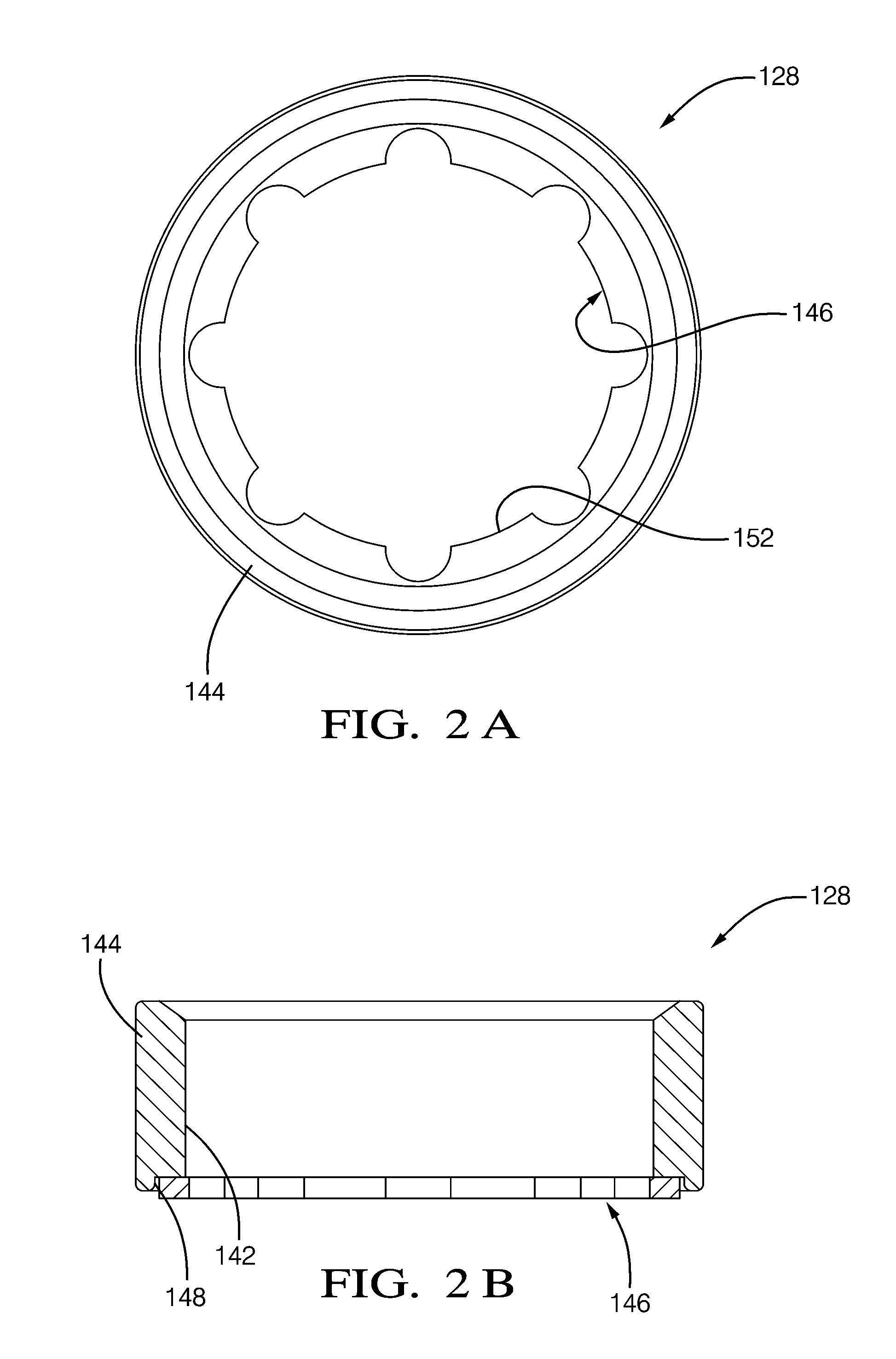
[0029]Now referring to FIGS. 2A-2D, isolation ring 128 is shown in an uncompressed state. Isolation member 146 may include a plurality of protrusions 152 that extend radially inward therefrom. Protrusions 152 serve to form an interference fit with fuel injector 24 in order to retain isolation ring 128 to fuel injector 24 before isolation ring 128 and fuel injector 24 are assembled into cylinder head 26.

[0030]Still referring to FIGS. 2A-2D, recess 148 is arranged to allow isolation member 146 to expand radially inward and radially outward when isolation member 146 is compressed axially. This is accomplished by allowing isolation member 146 to expand radially outward because radial clearance is provided between support member 144 and isolation member 146. This is also accomplished by allowing isolation member 146 to expand radially inward because recess 148 extends to center aperture 142, thereby bounding isolation member 146 only radially outward by support member 144.

[0031]Now refer...

second embodiment

[0032]In the second embodiment, support member 244 may be made of stamped sheet metal. This may result in hollow cavity 256 being formed at the end of support member 244 opposite recess 248. Isolation member 246 may then be injection molded to support member 244. In this way, isolation member 246 may be retained to support member 244.

[0033]Still referring to FIGS. 3A and 3B, recess 248 is arranged to allow isolation member 246 to expand radially inward when isolation member 246 is compressed axially. This is accomplished by allowing isolation member 246 to expand radially inward because recess 248 extends to center aperture 242, thereby bounding isolation member 246 only radially outward by support member 244.

third embodiment

[0034]Now referring to FIG. 4, a third embodiment is shown in an uncompressed state in which isolation ring 328 is shown at only a single radial location. In this embodiment, recess 348 bounds isolation member 346 both radially outward and radially inward over most of the axial length of isolation member 346. Recess 348 is arranged to allow isolation member 346 to expand radially outward and radially inward when isolation member 346 is compressed axially. This is accomplished by providing expansion cavities 358 at the open end of support member 344.


PUM


Abstract

A fuel injector-engine component assembly includes an engine component with a stepped bore defined along an axis and having a stepped bore stop surface facing axially upward. A fuel injector extending along the axis is disposed in the stepped bore and includes a fuel injector stop surface facing axially downward and axially opposing the stepped bore stop surface. An isolation ring is disposed between the engine component and fuel injector stop surfaces for axially isolating the fuel injector from the engine component. The isolation ring includes a rigid support member for limiting the axial motion of the engine component and fuel injector stop surfaces together. The isolation ring also includes a resilient and compliant isolation member located axially between the engine component and fuel injector stop surfaces to provide acoustic and thermal isolation between the fuel injector and the engine component below a predetermined pressure of the fuel injector.

Description

CROSS-REFERENCE TO RELATED APPLICATIONS[0001]This application claims the benefit of U.S. provisional patent application Ser. No. 61 / 330,629 filed May 3, 2010, the disclosure of which is hereby incorporated by reference in its entirety.TECHNICAL FIELD OF INVENTION[0002]The present invention relates to fuel injection systems of internal combustion engines; more particularly, to fuel injectors for direct injection; and most particularly to a device for acoustic and thermal isolation of a fuel injector from a cylinder head.BACKGROUND OF INVENTION[0003]Fuel injector systems that deliver fuel to the combustion chamber of an internal combustion engine have been known for many years. The typical fuel injection system draws fuel from a fuel tank to a fuel rail mounted adjacent to the cylinder bank of the engine. The fuel injectors are electro-mechanical devices that deliver fuel in precise amounts and times to the respective cylinder.[0004]While the engine is running, the valve within each f...

Claims


Application Information

Patent Timeline
Patent Type & Authority Applications(United States)
IPC IPC(8): F02M61/14
CPCF02M53/046F02M61/14F02M2200/09F02M2200/03F02M2200/858
Inventor XU, WENBINBRAUN, CHARLES W.PERRY, ROBERT B.FLYNN, VICKI A.
Owner DELPHI TECH INC
Why Eureka
Try Eureka