Mercury dosing method for fluorescent lamps

a fluorescent lamp and mercury vapor technology, applied in the manufacture of electric discharge tubes/lamps, discharge tubes luminescnet screens, electrode systems, etc., can solve the problems of increasing lamp cost, increasing lamp cost, and requiring special dosing equipment, so as to reduce lamp cost

Inactive Publication Date: 2011-11-03
GENERAL ELECTRIC CO
View PDF4 Cites 0 Cited by
  • Summary
  • Abstract
  • Description
  • Claims
  • Application Information

AI Technical Summary

Benefits of technology

[0012]Yet another benefit of the present disclosure is that the cost of the lamp may be reduced due to the elimination of mercury dispensers.

Problems solved by technology

Disadvantageously, this approach requires dosing the lamp with an excess of mercury since droplets of mercury can be left in the manufacturing equipment and the exhaust tube.
Disadvantageously, the technique to break the capsule to make the mercury available within the lamp is difficult and requires adding machines within the manufacturing process, thereby, presenting increased cost considerations.
However, amalgam dosing requires special dosing equipment and a means for positioning the amalgam inside the lamp.
Disadvantageously, this approach requires additional manufacturing parts, thereby increasing the cost of the lamp.
Furthermore, mercury is a hazardous material so various governmental regulations control the manner in which mercury, including mercury that is contained within articles of commerce such as fluorescent lamps is used.

Method used


Image

  • Mercury dosing method for fluorescent lamps
  • Mercury dosing method for fluorescent lamps
  • Mercury dosing method for fluorescent lamps

Examples


example 1

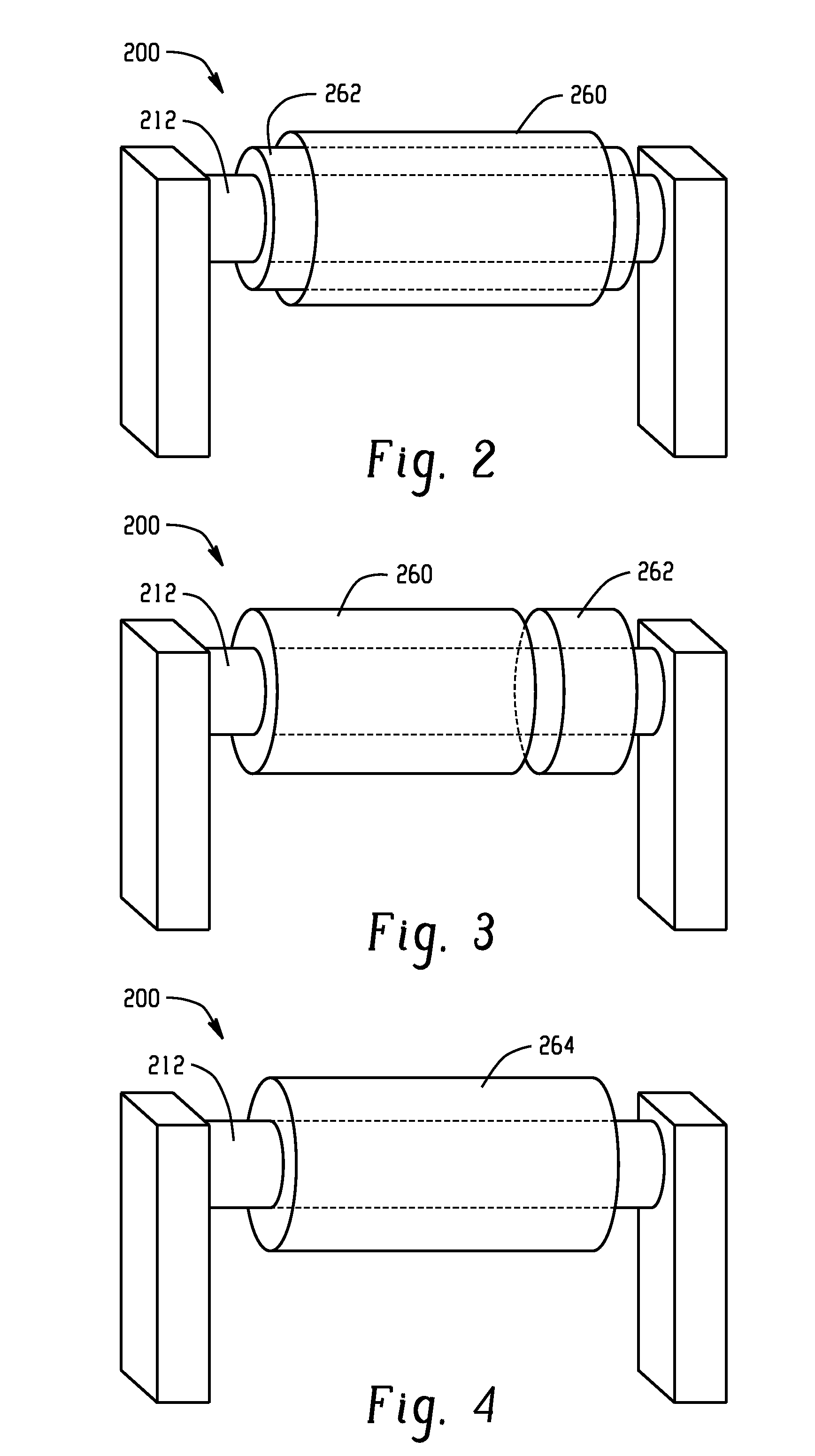
[0034]While a coiled electrode 200 in keeping with FIG. 2 is used in the following examples, it is to be understood that the coiled configuration has no critical bearing on the placement or function of the mercury and / or emission coatings. FIG. 2 is used to show the mercury containing composition disposed over the electron emission composition layer. In this example, a carbonate electron emissive composition is initially prepared. The coiled electrode is coated with a carbonate compound of barium, strontium, or calcium and up to about 5% of a zirconium oxide (ZrO2) additive to form the carbonate electron emissive composition layer. The constituents of the electron emissive material are suspended in butyl-acetate. A small amount is nitrocellulose (typically 1 m / m% of the electron emissive material) is also added to the suspension to ensure proper adhesion of the electron emissive material to the coil. The coated, coiled electrode is heated to about 1200° C. in order to decompose the ...

example 2

[0035]While a coiled electrode 200 in keeping with FIG. 3 is used in the following example, it is to be understood that the coiled configuration has no critical bearing on the placement or function of the mercury and / or emission coatings. In FIG. 3 the mercury containing composition coating is disposed adjacent the electron emission composition coating and directly on the electrode coil. In this example, the coiled electrode is coated with a carbonate electron emission composition as described in Example 1. The coated coiled electrode is heated to about 1200° C. in order to decompose the mixture into its active oxide phase and carbon dioxide as described in Example 1. The coated coiled electrode is then coated directly with a mercury-containing composition, such as mercury tungsten oxide (HgWO4), disposed adjacent the carbonate emission composition. The coated electrode is sealed into the chamber. During the sealing process the temperature of the coated electrode remained below 500°...

example 3

[0036]While a coiled electrode 200 in keeping with FIG. 4 is used in the following example, it is to be understood that the coiled configuration has not critical bearing on the placement or function of the mercury and / or emission coatings. In FIG. 4, the coiled electrode is coated with a composition formed by mixing an air stable electron emissive composition and a mercury containing composition, thus requiring the deposition of only one mercury dosing layer. Fine powders of mercury tungsten oxide and barium calcium tungsten oxide, an air-stable electron emissive composition, were mixed in a mass ratio of 14:86, respectively. The resulting mixture was suspended in butyl acetate. The coiled electrode was then coated with the formed composition. The coated electrode is sealed into the chamber. During the sealing process the temperature of the coated electrode remained below 500° C. Current is passed through the the coated electrode to heat up to about 300° C. not higher than 500° C. t...


PUM


Abstract

A fluorescent lamp includes a discharge tube having an inner wall forming a discharge chamber. One or more coiled electrodes are disposed within the discharge tube. A mercury containing composition is disposed on at least one coiled electrode.

Description

BACKGROUND OF THE DISCLOSURE[0001]The present disclosure relates generally to a low pressure mercury vapor discharge lamp and more particularly to a hot cathode fluorescent lamp including a mercury dosing apparatus and method.[0002]Fluorescent lamps have found widespread acceptability in the market place for a number of applications and are available in a variety of shapes and forms. For example, the lamps may be linear, curvilinear, U-bent or compact in shape as will be familiar to those having ordinary skill in the art. Typically, fluorescent lamps include a light-transmissive glass discharge tube with means, such as electrodes, providing an electric discharge to the interior of the discharge tube. A phosphor layer typically applied to the inner wall surface of the discharge tube comprises the source of the light that the lamp emits. A fill gas and mercury are sealed within the discharge tube and the mercury functions to excite the phosphors' electrons resulting in the production ...

Claims


Application Information

Patent Timeline
Patent Type & Authority Applications(United States)
IPC IPC(8): H01J61/20H01J9/02
CPCH01J61/067H01J61/72H01J61/24
Inventor SOMOGYVARI, ZOLTANBALAZS, LASZLO
Owner GENERAL ELECTRIC CO
Why Eureka
Try Eureka