Combining multiple laser beams to form high repetition rate, high average power polarized laser beam

a laser beam and laser beam technology, applied in semiconductor lasers, instruments, non-linear optics, etc., can solve the problem of low efficiency of the combinator

Inactive Publication Date: 2011-11-03
ELECTRO SCI IND INC
View PDF4 Cites 58 Cited by
  • Summary
  • Abstract
  • Description
  • Claims
  • Application Information

AI Technical Summary

Benefits of technology

[0016]In some additional, alternative, or cumulative exemplary embodiments, the EOM alternates the laser pulses of the two pulsed laser beams to provide a composite repetition rate of laser pulses from both la

Problems solved by technology

The described configuration of seed pulses working with an optical amplifier is of a standard design because the combiner has low efficiency.
These paten

Method used


Image

  • Combining multiple laser beams to form high repetition rate, high average power polarized laser beam
  • Combining multiple laser beams to form high repetition rate, high average power polarized laser beam
  • Combining multiple laser beams to form high repetition rate, high average power polarized laser beam

Examples


Embodiment Construction

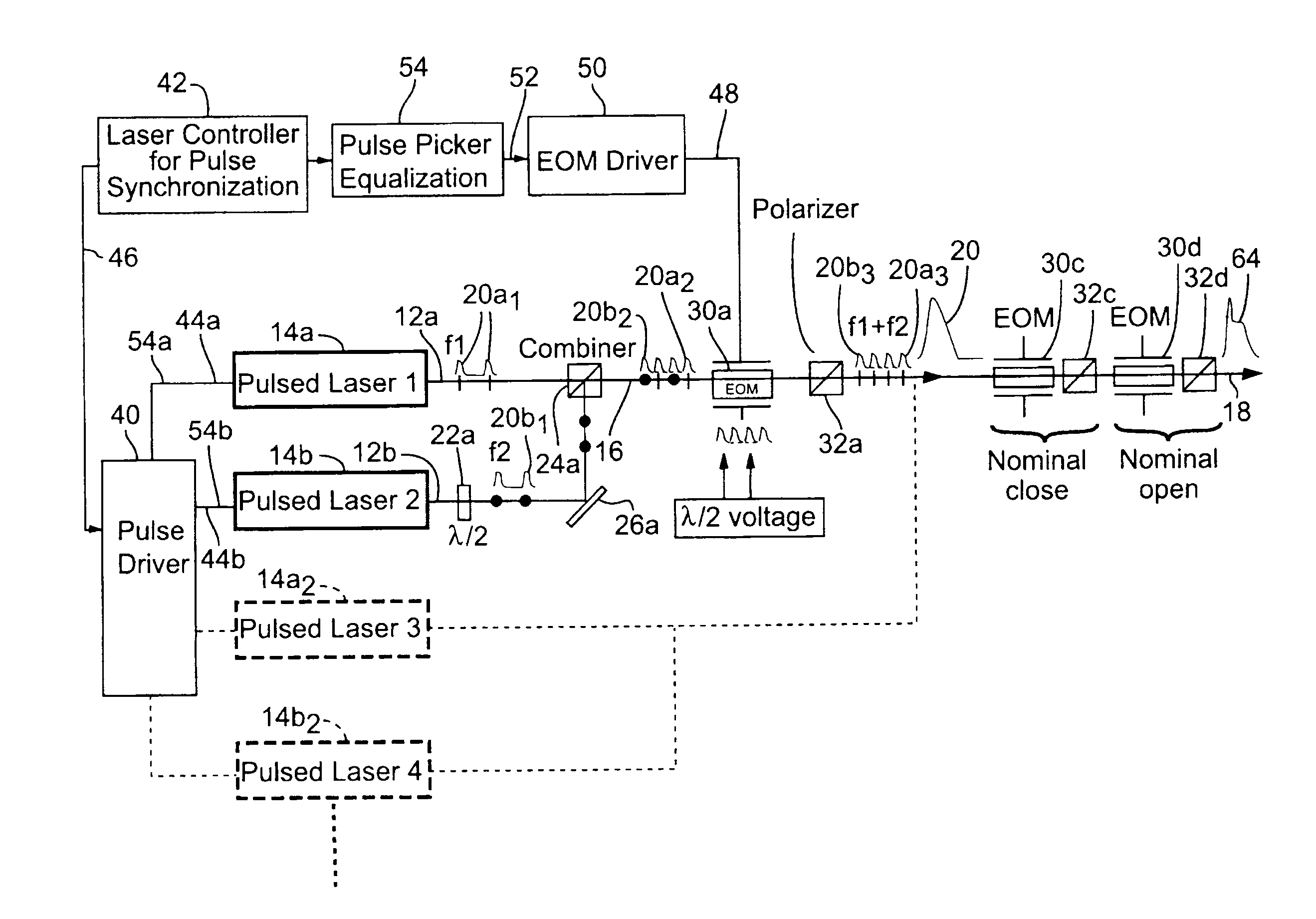
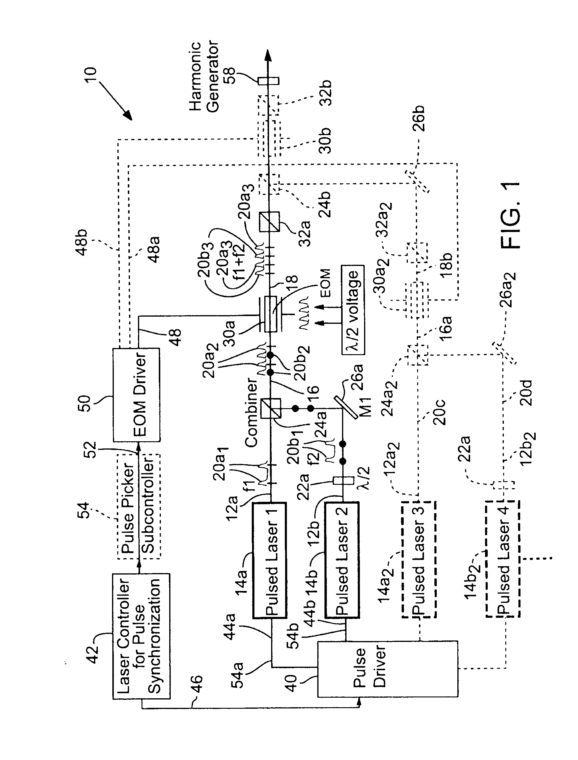
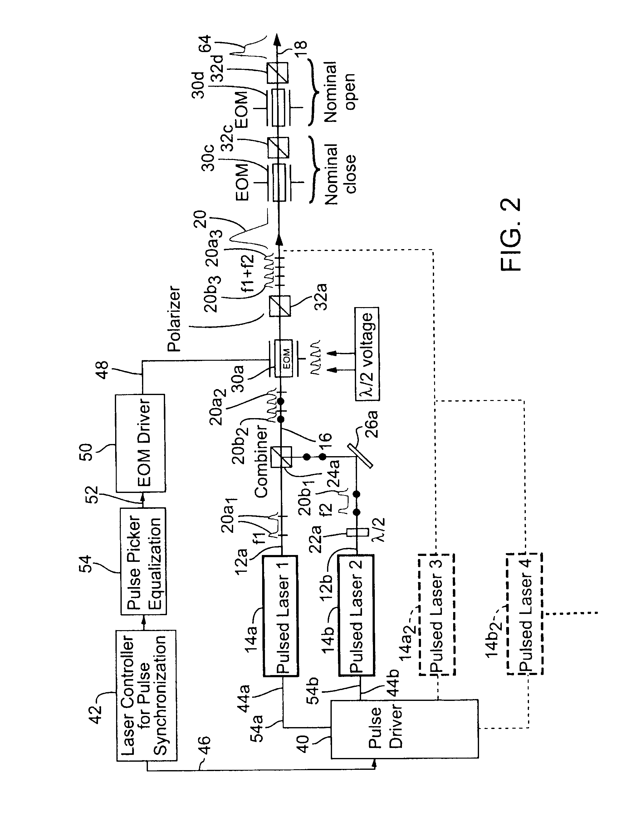
[0046]FIG. 1 shows an exemplary laser system 10 for combining laser beam paths 12a and 12b from respective pulsed lasers 14a and 14b to produce along a combined beam path 16 a composite output beam 18 that may have one or more properties that are beyond the individual capabilities of either pulsed laser 14a or 14b. Almost any type of pulsed laser 14 is suitable for use with the beam combining techniques described herein. Exemplary pulsed lasers 14 include, but are not limited to, diode-pumped solid-state lasers, fiber lasers, diode lasers, semiconductor lasers, gas lasers, or copper vapor lasers.

[0047]Some of such pulsed lasers 14 may emit a laser pulse 20 having a pulse width as short as a few femtoseconds while others may emit a laser pulse 20 having a pulse width as long as several 100 nanoseconds or longer, or any of various ranges of pulse widths in between. In some embodiments, the pulse widths may be from about 10 femtoseconds to about 1 picosecond, from about 1 picosecond to...


PUM


Abstract

Two pulsed lasers (14) or sets of lasers propagate beams of pulses (20) having orthogonally related polarization states. A beam combiner (24) combines the orthogonal beams to form a combined beam propagating along a common beam path (16) to intersect an optical modulator (30) that selectively changes the polarization state of selected pulses of either beam to provide a composite beam (18) including similarly polarized pulses from the orthogonal beams. The composite polarized beam has a composite average power and a composite repetition rate that are greater than those provided by either laser. The optical modulator can also selectively control the polarization states of pulses from either laser to pass through or be blocked by a downstream polarizer (32). Additional modulators may facilitate pulse shaping of the pulses. The system is scalable by addition of sets of single lasers or pairs of lasers with beam combiners and modulators.

Description

RELATED APPLICATIONS[0001]This application claims benefit of International Application No. PCT / US2009 / 038559, filed Mar. 27, 2009, which claims benefit of U.S. Provisional Patent Application Nos. 61 / 041,132 and 61 / 041,143, both of which filed Mar. 31, 2008.COPYRIGHT NOTICE[0002]©2010 Electro Scientific Industries, Inc. A portion of the disclosure of this patent document contains material that is subject to copyright protection. The copyright owner has no objection to the facsimile reproduction by anyone of the patent document or the patent disclosure, as it appears in the Patent and Trademark Office patent file or records, but otherwise reserves all copyright rights whatsoever. 37 CFR § 1.71(d).TECHNICAL FIELD[0003]The disclosure concerns combining laser beams and, in particular, to optical modulator applications associated with combining laser beams to increase repetition rate.BACKGROUND INFORMATION[0004]Laser beam combining has been used for increasing power, for double pulse proc...

Claims


Application Information

Patent Timeline
IPC IPC(8): G02F1/03G02F1/35H01S3/067
CPCH01S3/005H01S3/0085H01S3/0092H01S3/0941H01S3/10061H01S3/115H01S3/10046H01S3/2383H01S5/0085H01S5/0092H01S5/4012H01S5/4025H01S3/117
Inventor PENG, XIAOYUANJORDENS, WILLIAM J.
Owner ELECTRO SCI IND INC
Why Eureka
Try Eureka