Apparatus for capturing heat from a stove

a technology for capturing heat and stoves, applied in the field of apparatus for capturing heat from stoves, can solve the problems of tars and creosotes accumulating, the merit of trying to recover heat from the chimney gasses of efficient stoves, and dramatically reducing the convective ‘draw’ required for good combustion, so as to save costs for the householder and reduce carbon emissions

Inactive Publication Date: 2011-11-10
KINXERG LTD
View PDF37 Cites 6 Cited by
  • Summary
  • Abstract
  • Description
  • Claims
  • Application Information

AI Technical Summary

Benefits of technology

[0012]During operation of the stove, operation in the first mode minimises the hot air flowing in the heat exchanger, and hot air carrying a maximum amount of heat is passed to the surroundings of the stove. Therefore, a minimum of heat is transferred to the water and the stove acts as a room heater. However, during operation in the second mode, heat is transferred from the heated air to water flowing within the water side of the heat exchanger. This later condition allows heat from the stove to be transferred to another heating system, hot water system, etc.
[0014]Air within the air duct typically flows in opposite directions in the first and second modes. Most typically, in the first mode it flows generally upward (although it may be that it does not flow upward throughout its entire flow path), being driven by natural convection. Such an arrangement has been found to offer a system in which the flow of air and transfer of heat can be controlled predictably and easily.
[0022]Embodiments may further include an outer cover that creates a second air duct between itself and the cover. This can be disposed to increase the efficiency of the apparatus. In such embodiments, air can be caused to flow in the second air duct by natural convection to reduce the outer casing temperature of the apparatus.
[0023]Preferably the control means is fail-safe, such that it diverts air from the heat exchanger in the event of there being insufficient flow of water within its water side. This ensures that the heat exchanger is protected from damage by overheating.
[0028]In embodiments of this aspect of the invention, the control means may operate to minimise the flow of heated air from the stove to the heat exchanger when the pump of the circulation system is not operational.

Problems solved by technology

There is little merit in trying to recover heat from the chimney gasses of efficient stoves since only a small part of the total heat output of such stoves is carried in the chimney gasses.
Taking heat from the chimney gasses may cause problems: cooler gasses tend to form condensates in the chimney, which can cause tars and creosotes to accumulate in the chimney, and an insufficiently warm chimney can dramatically reduce the convective ‘draw’ required for good combustion.
Heat exchangers that are exposed to combustion gasses are likely to suffer from fouling by combustion products.
Moreover, if a heat exchanger is located in a chimney, it is not an easy matter to divert heat from the heat exchanger such that it can be discharged into a room surrounding the stove.

Method used


Image

  • Apparatus for capturing heat from a stove
  • Apparatus for capturing heat from a stove
  • Apparatus for capturing heat from a stove

Examples


Embodiment Construction

[0037]An embodiment of the invention will now be described in detail, by way of example, and with reference to the accompanying drawings.

[0038]As an introduction to the embodiment, operation of a modern wood-burning stove will now be discussed.

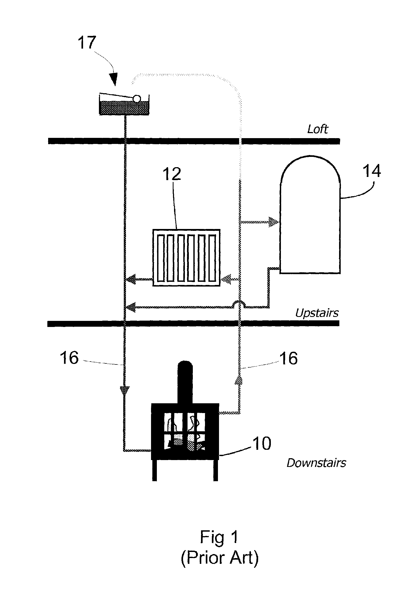
[0039]Heat transfer from a stove to its surroundings (typically, a room in a building) occurs by way of radiation (A) and convection (B) from the surfaces of the stove to air within a room in which the stove is located and there is also heat lost (C) up the chimney 28. For a well-designed stove, the chimney loss should be less that 30%, and may be less than 20% for some of the most efficient new designs. The proportions of radiative and convective heat transfer can vary depending on the design and temperature of the stove sides.

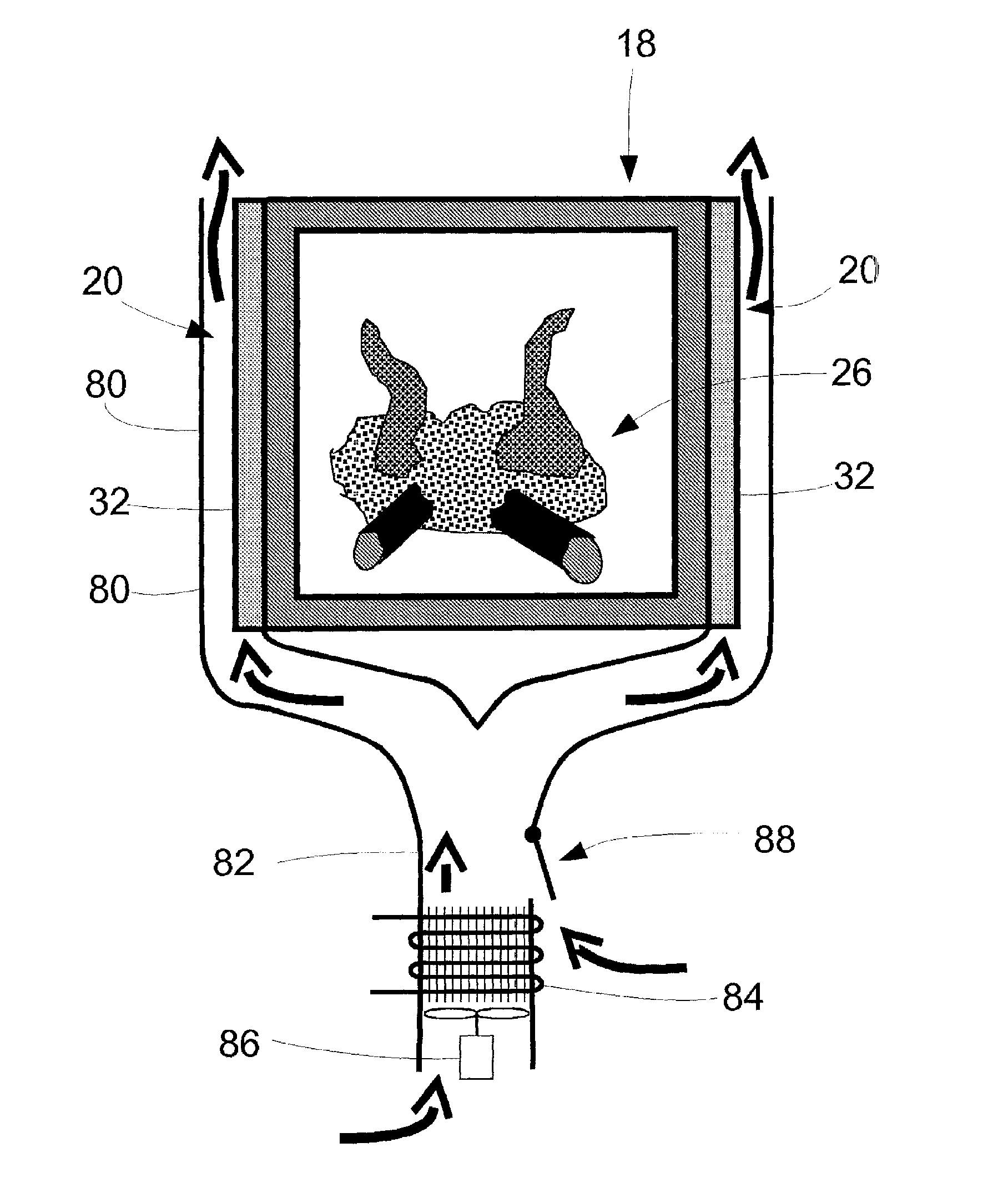
[0040]For a stove 18 with finned sides 20, as shown in FIG. 2, the majority of the heat generated by the burning fuel is transferred by convection from the stove sides 20, with a higher proportion of radiant heat transf...


PUM


Abstract

Apparatus for capturing heat from a stove to enable it to be transferred to a central heating system is disclosed. The apparatus comprises an air-water heat exchanger, the heat exchanger having an air side and a water side and being operative to transfer heat between air on the air side and water flowing in channels in the water side. The apparatus includes an air duct through which air heated by a stove can pass by convection to contact the air side of the heat exchanger and control means operable to control the amount of air flowing to the heat exchanger. The control means may include a fan that can be operated to direct the flow of air to the heat exchanger.

Description

CROSS REFERENCE TO RELATED APPLICATION[0001]This application is a national stage entry of PCT / GB2010 / 050013 filed Jan. 6, 2010, under the International Convention claiming priority over GB Patent Application No. 0900259.3 filed Jan. 9, 2009 and GB Patent Application No. 0904718.4 filed Mar. 19, 2009.BACKGROUND TO THE INVENTION[0002]1. Field of the Invention[0003]This invention relates to apparatus for capturing heat from a stove. In particular, it relates to apparatus for capturing heat from a stove whereby that heat can be transferred to a central heating system. In the context of this invention, the term ‘stove’ is used as a generic term for apparatus to allow enclosed burning of solid fuels. It does not necessarily imply a stove that can be used for cooking, although some do offer cooking or warming plates. Moreover, the invention is described principally in connection with wood-burning stoves, because this is the context in which the greatest potential benefit can be obtained. H...

Claims


Application Information

Patent Timeline
Patent Type & Authority Applications(United States)
IPC IPC(8): F24B1/00
CPCF24B1/187F24B7/025F24H6/00F24D2200/06F24D11/004Y02B30/13F24B7/007F24B7/045F24B9/04F24C13/00
Inventor REDFORD, SIMON
Owner KINXERG LTD
Why Eureka
Try Eureka