

Radiation-Induced Thickening and Radiation-Induced Triggering for Set-On-Command Sealant Compositions and Methods of Use
a technology of radiation-induced thickening and radiation-induced trigger, which is applied in the direction of sealing/packing, chemistry apparatus and processes, and wellbore/well accessories. it can solve the problems of increasing the mechanical strength of the sealant composition, and achieve the effect of rapid curing of cement mixture, sufficient strength and sufficient strength
- Summary
- Abstract
- Description
- Claims
- Application Information
AI Technical Summary
Benefits of technology
Problems solved by technology
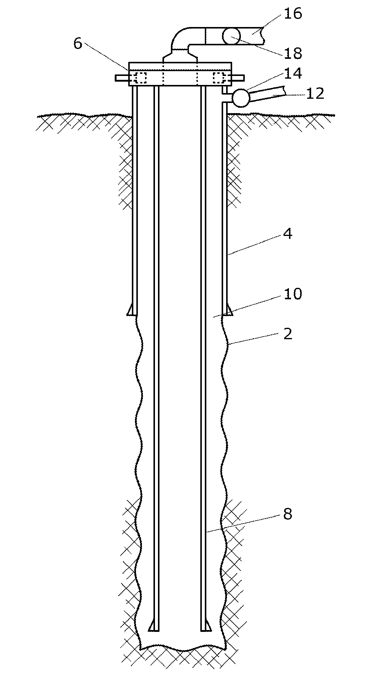
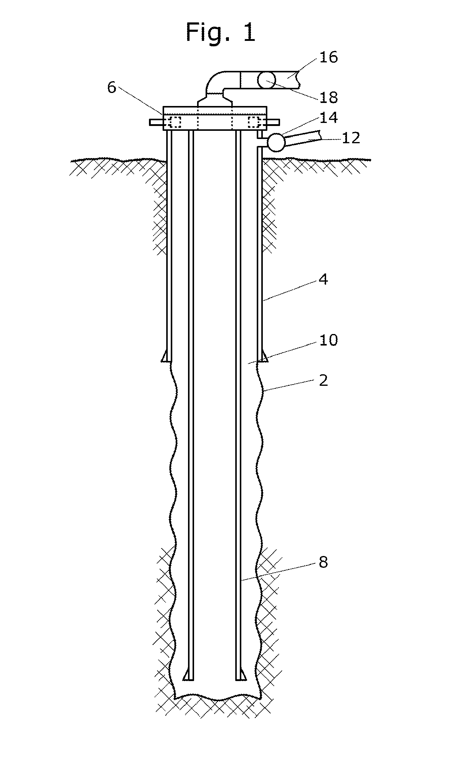
Method used
Image

Examples
example 1
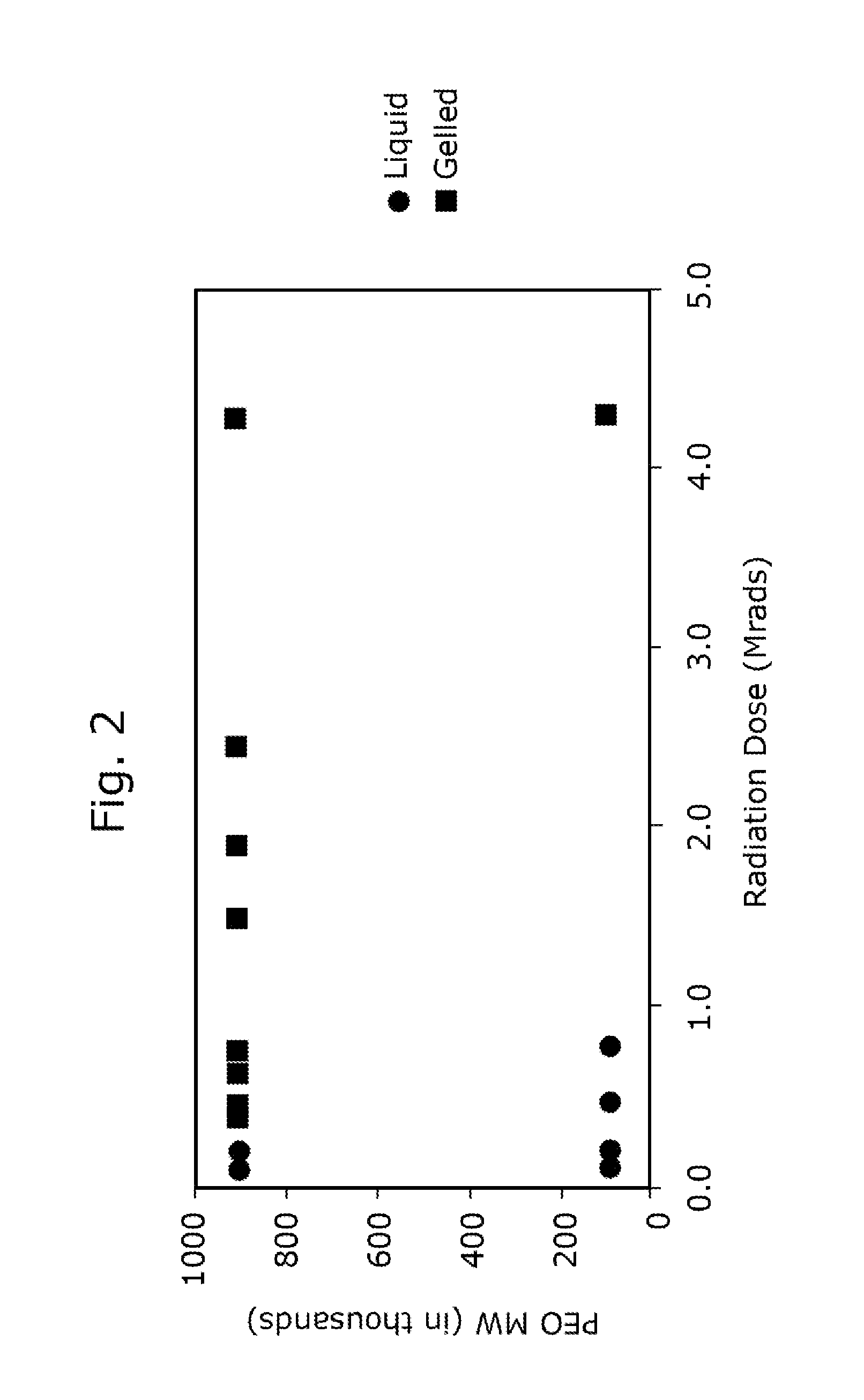
[0126]800 grams of a Class H cement was mixed with 320 mL of water (to give a water-to-cement, w / c, ratio of 0.40) and 0.5% bwoc of a 900,000 MW PEO (polyethylene oxide) to form a slurry. The slurry also contained 0.50% bwoc maltrodextrin, a cement set retarder. The slurry was mixed for 45 seconds in a Waring blade mixer at high shear. The slurry was split into two samples. One sample was exposed to 4.3 Mrads of gamma radiation exposure from a Co-60 source while the other was kept as the control. The control sample, that was not irradiated was still fluid (yield point measured at 3.5 Pa) whereas the gamma-irradiated sample had cross-linked and was totally solid.
example 2
[0127]Several slurries were prepared using a Class H cement, water (to give a water-to-cement, w / c, ratio of 0.40) with two different PEOs (100,000 MW and 900,000 MW). Other components in the slurries were a polycarboxylate ether (dispersant), Diutan gum (viscosity modifier) and maltodextrin (retarder). The mix-designs for the slurries are given in Table 3.
TABLE 3Mix designs for the slurries used in cross-linking experiments.Mix DesignMIX #1MIX #2MIX #3MIX #4MIX #5MIX #6Cementgrams800800800800800800watergrams316.4316.4320320320320Retarder (Maltodextrin)grams444444Dispersant NameADVA 575ADVA 575Melflux 1641Melflux 1641Melflux 2651Melflux 2651Disperant Total Solids0.400.401.001.001.001.00Dispersantgrams662.42.42.42.4VMA (Diutan Gum)grams3.23.23.23.23.23.2PEO MW100,000900,000100,000900,000100,000900,000PEOgrams444444
[0128]All of the slurries were exposed to 4.3 Mrads of gamma radiation from a Co-60 source and were found to cross-link and gel on exposure to gamma radiation while non-rad...
example 3
[0129]800 grams of a Class H cement was mixed with 320 mL of water (w / c=0.40) and 0.5% bwoc of a 360,000 MW poly (vinyl pyrrolidone) to form a slurry. The slurry also contained 0.50% bwoc maltrodextrin, a cement set retarder. The slurry was mixed for 45 seconds in a Waring blade mixer at high shear. The slurry was split into two samples. One sample was exposed to 4.3 Mrads of gamma radiation exposure from a Co-60 source while the other was kept as the control. The control sample that was not irradiated was still fluid, with a yield point measured at 150 Pa, whereas the gamma-irradiated sample had cross-linked and was totally solid.
PUM
| Property | Measurement | Unit |
|---|---|---|
| thickness | aaaaa | aaaaa |
| thickness | aaaaa | aaaaa |
| thickness | aaaaa | aaaaa |
Abstract
Description
Claims
Application Information