Membrane electrolyzer and hemodialysis system using the same

a hemodialysis system and membrane electrolyzer technology, applied in the direction of dialysis, apparatus sterilization, water/sewage treatment by oxidation, etc., can solve the problems of high cost of sorbent hemodialysis, high cost of sorbent based dialysis, and high cost of sorbent cartridges

Inactive Publication Date: 2011-11-10
C TECH BIOMEDICAL
View PDF0 Cites 89 Cited by
  • Summary
  • Abstract
  • Description
  • Claims
  • Application Information

AI Technical Summary

Benefits of technology

[0009]In accordance with one embodiment, a sorbent hemodialysis system is provided. The system comprises a dialyzer configured to receive a flow of clean dialysate from a reservoir, the dialyzer configured to output an unclean dialysate flow. The system also comprises a sorbent component having a urease section and a sorbent section through which the unclean dialysate flow from the dialyzer passes, the sorbent component configured to remove urea from the unclean dialysate flow. The system further comprises a membrane electrolyzer configured to receive at least a portion of said clean dialysate flow and to separate the dialysate flow into an acidic component flow and a base component flow. The system also comprises a mixing conduit configured to combine the base component flow from the

Problems solved by technology

However, conventional sorbent dialysis treatment can be costly, particularly for patients that must receive treatment every day or every other day.
One contributor to the cost of sorbent based dialysis is the cost of the sorbent cartridge, which costs approximately $30 per cartridge, of which about $15 is th

Method used


Image

  • Membrane electrolyzer and hemodialysis system using the same
  • Membrane electrolyzer and hemodialysis system using the same
  • Membrane electrolyzer and hemodialysis system using the same

Examples


Embodiment Construction

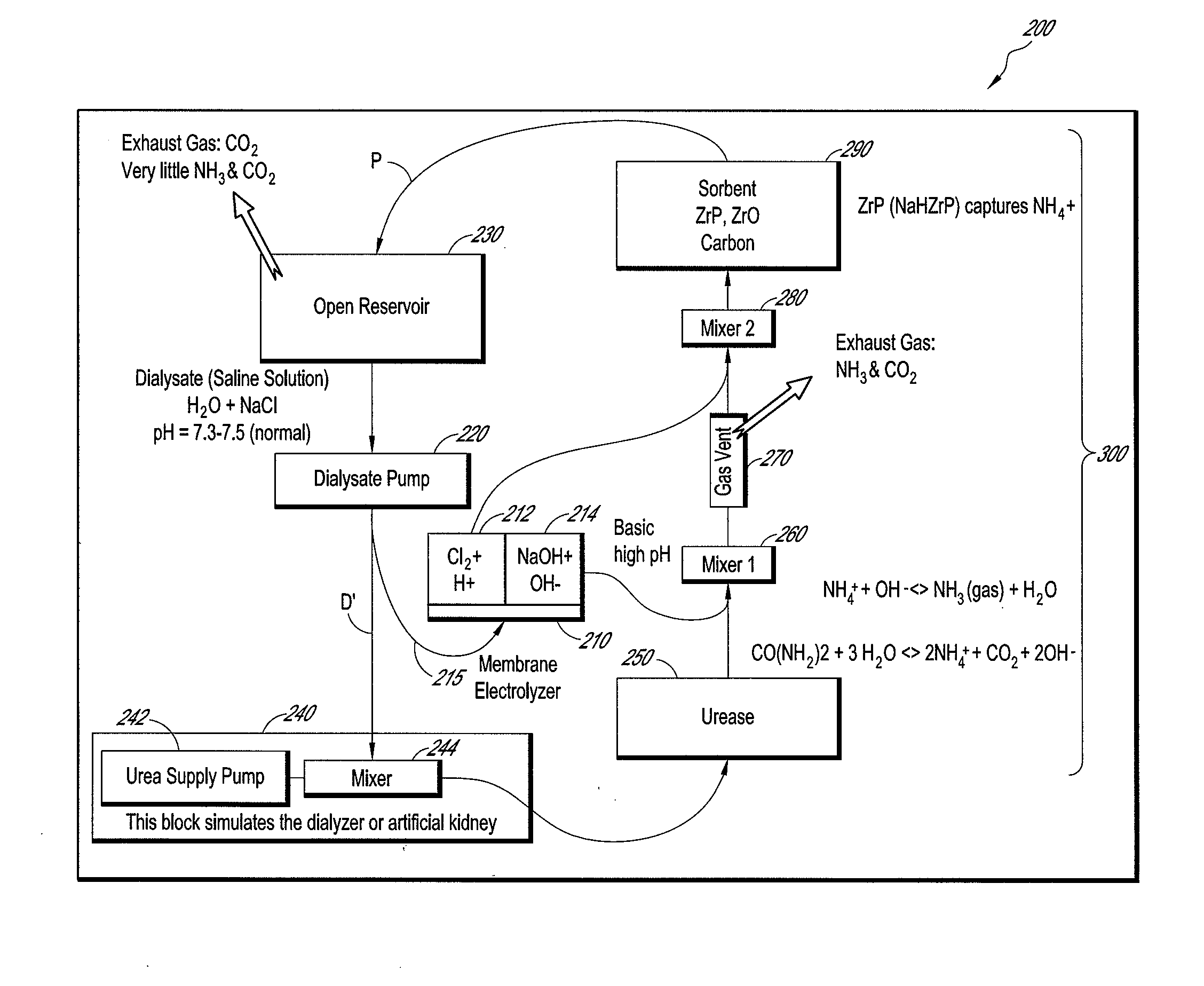
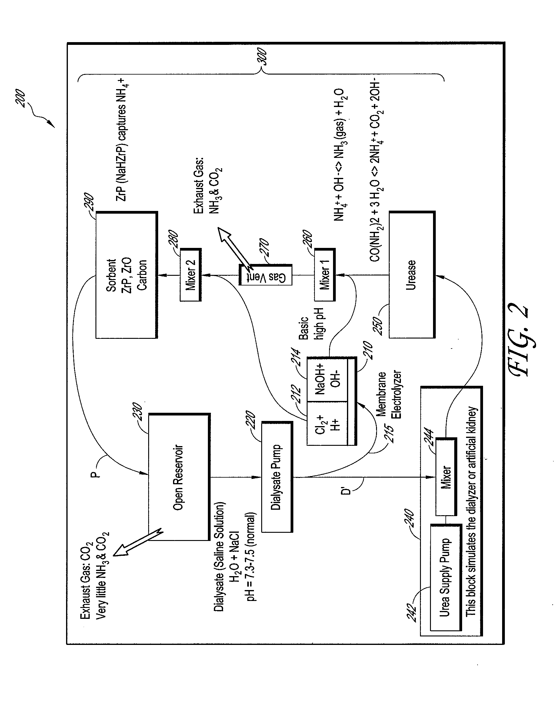
[0015]FIG. 2 shows a portion of one embodiment of an improved sorbent hemodialysis system 200. In particular, FIG. 2 shows a dialysate flow path or circuit P of the hemodialysis system 200. In the illustrated embodiment, a membrane electrolyzer 210 receives at least a portion 215 of a dialysate D′ flow pumped by a dialysate pump 220 in fluid communication with a dialysate reservoir 230. The remaining dialysate flow D′ is pumped through the dialyzer 240, which can have a urea supply pump 242 and a mixer 244. The dialysate flow loaded with urea D exits the dialyzer 240 and passes through a urease section 250.

[0016]The membrane electrolyzer 210 splits the dialysate flow 215 into an acidic component 212 and a base component 214. The base component 214 is added to the dialysate flow D downstream of the urease section 250 via a mixer 260, and is used to raise the pH of the dialysate flow D to effect “blowing off” of ammonia and carbon dioxide as a gas via a gas vent 270. Then, the acidic ...


PUM


Abstract

A sorbent hemodialysis system includes a dialyzer configured to receive a flow of clean dialysate from a reservoir and to output an unclean dialysate flow. The system also includes a sorbent component having a urease section and a sorbent section through which the unclean dialysate flow from the dialyzer passes, wherein the sorbent component removes urea from the dialysate. The system further comprises a membrane electrolyzer that receives at least a portion of said clean dialysate flow and separates the dialysate flow into an acidic component flow and a base component flow. A mixing conduit combines the base component flow from the membrane electrolyzer and an output dialysate solution from the urease section of the sorbent component to separate the dialysate solution into an ammonia gas amount and ammonia liquid amount. A gas vent is used to vent the ammonia gas amount, and the sorbent section with a suitable amount of zirconium phosphate (ZrP) removes the ammonia liquid amount from the unclean dialysate flow before flowing the clean dialysate to the reservoir. The system can further include a second mixing conduit upstream of the sorbent section of the sorbent component, the second mixing conduit combining the acidic component flow and the ammonia liquid amount in the dialysate solution to increase the pH of the dialysate solution to about 7.5 prior to returning to the reservoir.

Description

CROSS-REFERENCE TO RELATED APPLICATIONS[0001]This application claims the benefit of U.S. Provisional Application No. 61 / 331,502, filed May 5, 2010, the entire contents of which are hereby incorporated by reference and should be considered a part of this specification.BACKGROUND[0002]1. Field[0003]The present invention is directed to a sorbent hemodialysis system, and more particularly to a sorbent hemodialysis system with a membrane electrolyzer.[0004]2. Description of the Related Art[0005]In conventional sorbent based hemodialysis systems, urease enzyme is used to convert urea to NH4+ which is then removed from the dialysate via ion exchange with ZrP (NaHZrP) in a sorbent cartridge. A typical sorbent cartridge designed for every other day dialysis treatments removes about 30 gm of urea and contains about 1,767 grams of ZrP.[0006]The typical sorbent based hemodialysis process 100 is shown in FIG. 1. A dialysate D, which is a “normal” saline solution having a pH of approximately 7.5,...

Claims


Application Information

Patent Timeline
IPC IPC(8): B01D61/26C12M1/12C25B1/00B01D61/28
CPCB01D61/44A61M1/1696
Inventor BRAIG, JAMES
Owner C TECH BIOMEDICAL
Why Eureka
Try Eureka