Infrared light detector and production thereof

a technology of infrared light and detector, which is applied in the direction of instruments, electrical devices, radiation pyrometry, etc., can solve the problems of high cost of such multiple infrared light sensors b>101/b>, and achieve the effect of stable mechanical bond

Active Publication Date: 2011-11-10
AVAGO TECH INT SALES PTE LTD
View PDF2 Cites 10 Cited by
  • Summary
  • Abstract
  • Description
  • Claims
  • Application Information

AI Technical Summary

Benefits of technology

The second substrate is preferably bonded to the first substrate. The infrared light detector thereby has a stable mechanical bond between the first substrate and the second substrate, wherein the substrate is arranged at only a small distance from the first substrate.
The infrared light detector preferably has a third substrate that is arranged on the side of the first substrate that faces away from the second substrate. The third substrate preferably has an evaluation circuit to evaluate an electrical signal of the sensor chip. An activation of the sensor chip that leads to the electrical signal of the sensor chip can be evaluated by the evaluation circuit. The evaluation circuit is preferably integrated into the third substrate and / or settled outside of the third substrate. If the evaluation circuit is arranged integrated into the third substrate, the infrared light detector has a compact design. It is also preferred that the third substrate is made of a silicon wafer.

Problems solved by technology

However, the cost of such multiple infrared light sensors 101 would be too high.

Method used


Image

  • Infrared light detector and production thereof
  • Infrared light detector and production thereof
  • Infrared light detector and production thereof

Examples


Embodiment Construction

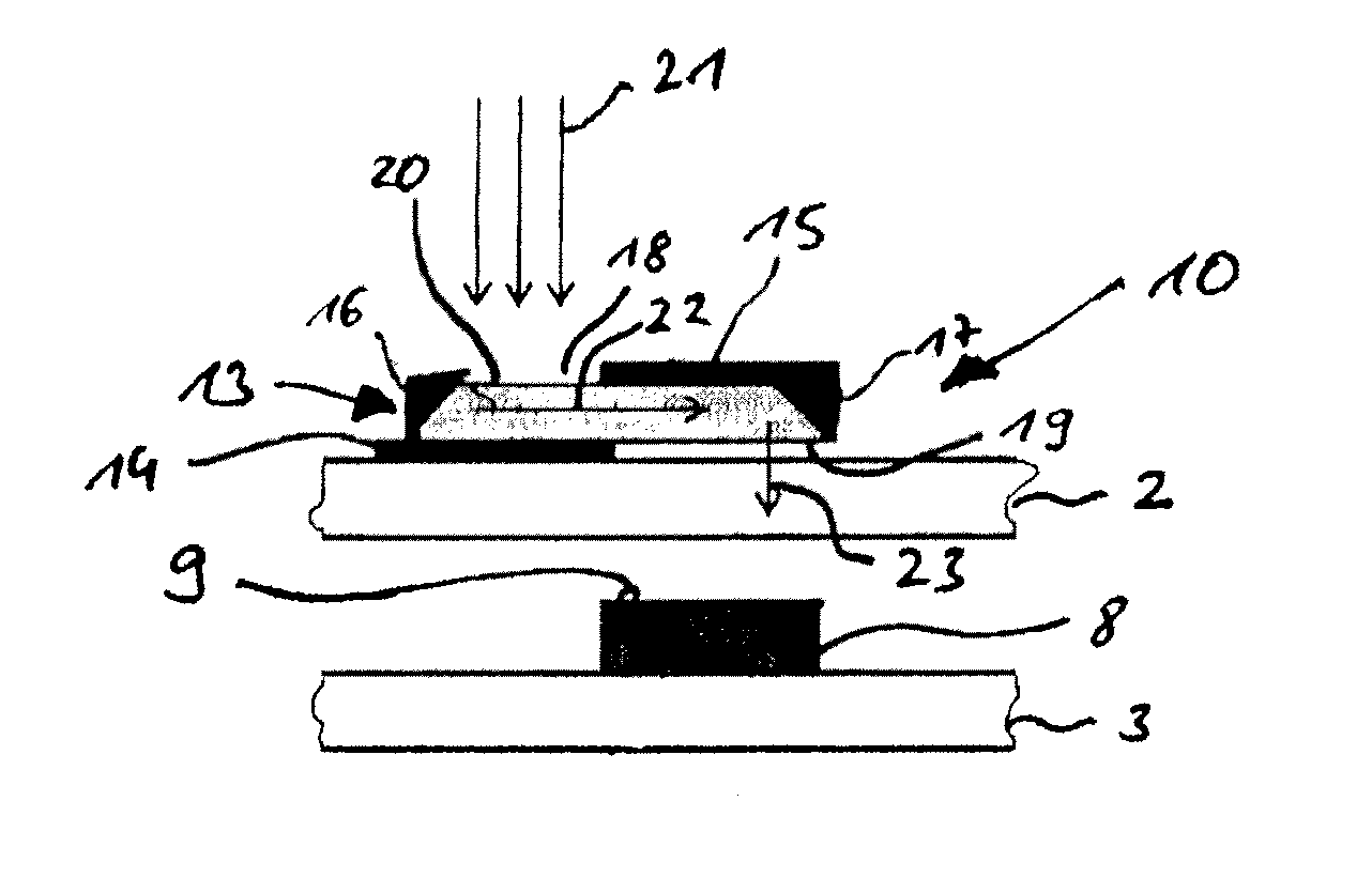
As is apparent from FIG. 1, an infrared light detector 1 has a first substrate 2 that is fashioned as a plate. The infrared light detector 1 also has a second substrate 3 that has the same dimensions as the first substrate 2 and is arranged at a distance above (as viewed in FIG. 1) the first substrate 2. A third substrate 4 that has the same dimensions as the first substrate 2 is provided below (as viewed in FIG. 1) the first substrate at a distance. Both the second substrate 3 and the third substrate 4 are fastened at their outer edges to the first substrate 2 by means of a bonded attachment 4, such that one cavity is fashioned between the first substrate 2 and the second substrate 3 and another cavity is fashioned between the first substrate 2 and the third substrate 4.

Four sensor chips 8 that are located at identical distances from one another are arranged on the top side 6 of the first substrate 2. Each sensor chip 8 respectively has an exposure area 9 at its top side. A window ...


PUM


Abstract

An infrared light detector has a first substrate having a sensor chip thereon that has an exposure surface that can be irradiated with infrared light, the sensor chip converting the incident infrared light into an electrical signal. The infrared light detector also has a second substrate having a window therein that is located adjacent to the exposure surface of the sensor chip, the window masking infrared light of a predetermined wavelength. The size (dimensions) of the window and the distance of the window with respect to the exposure surface are dimensioned to cause infrared light passing through the window to completely strike the exposure area of the sensor chip.

Description

BACKGROUND OF THE INVENTION1. Field of the InventionThe invention concerns an infrared light detector, a method to produce the infrared light detector and the use of the infrared light detector as a sensor to detect gas.2. Description of the Prior ArtTo detect gas it is known to use infrared light that lies within a wavelength range from 3 to 5 μm. The gas to be detected is exposed with a light source that is suitable to emit the infrared light in this wavelength range, wherein a portion of the infrared light is absorbed by the gas so that a residual light remains. The residual light can be measured with an infrared light sensor with which the wavelength range and / or the intensity of the residual light can be detected and can correspondingly be transduced into an electrical signal. Given a suitable evaluation the type and the content of the detected gas can be concluded on the base of the electrical signal.A conventional infrared light sensor 101 is shown in FIG. 4, which infrared l...

Claims


Application Information

Patent Timeline
Patent Type & Authority Applications(United States)
IPC IPC(8): G01J5/10H01L31/18
CPCG01J5/0014G01J5/04G01J5/045G01J5/10G01J5/0803G01J5/0846G01J5/0862G01J5/08G01J5/0802
Inventor GIEBELER, CARSTEN
Owner AVAGO TECH INT SALES PTE LTD
Why Eureka
Try Eureka