Encapsulated micro-electro-mechanical device, in particular a MEMS acoustic transducer

a micro-electromechanical and acoustic transducer technology, applied in the direction of microstructural devices, microstructure devices, electric transducers, etc., can solve the problems of complex or costly known solutions, difficult to apply metal coatings, and inability to adapt to devices

Active Publication Date: 2011-11-10
STMICROELECTRONICS SRL
View PDF0 Cites 44 Cited by
  • Summary
  • Abstract
  • Description
  • Claims
  • Application Information

AI Technical Summary

Problems solved by technology

However, known solutions are either complex or costly, and thus leave room for improvement.
In particular, in certain solutions it is problematical to apply the metal coating via usual sputtering operations on account of the depth of the structures in the cap.
Furthermore, in all cases, the process is costly and far from suited to devices, such as microphones, that are to be used in cell phones and the like, the costs of which should be as low as possible.

Method used


Image

  • Encapsulated micro-electro-mechanical device, in particular a MEMS acoustic transducer
  • Encapsulated micro-electro-mechanical device, in particular a MEMS acoustic transducer
  • Encapsulated micro-electro-mechanical device, in particular a MEMS acoustic transducer

Examples


Embodiment Construction

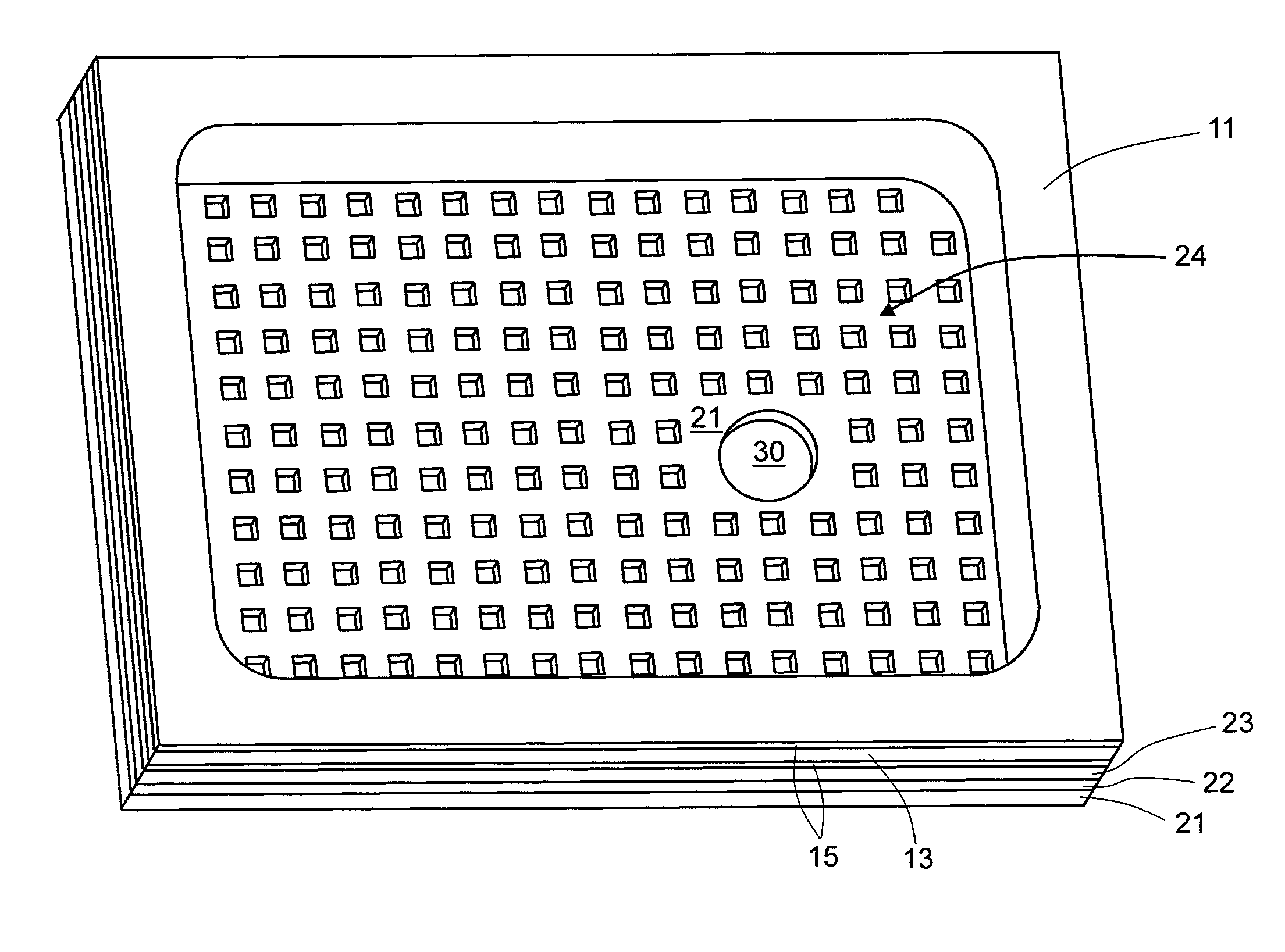
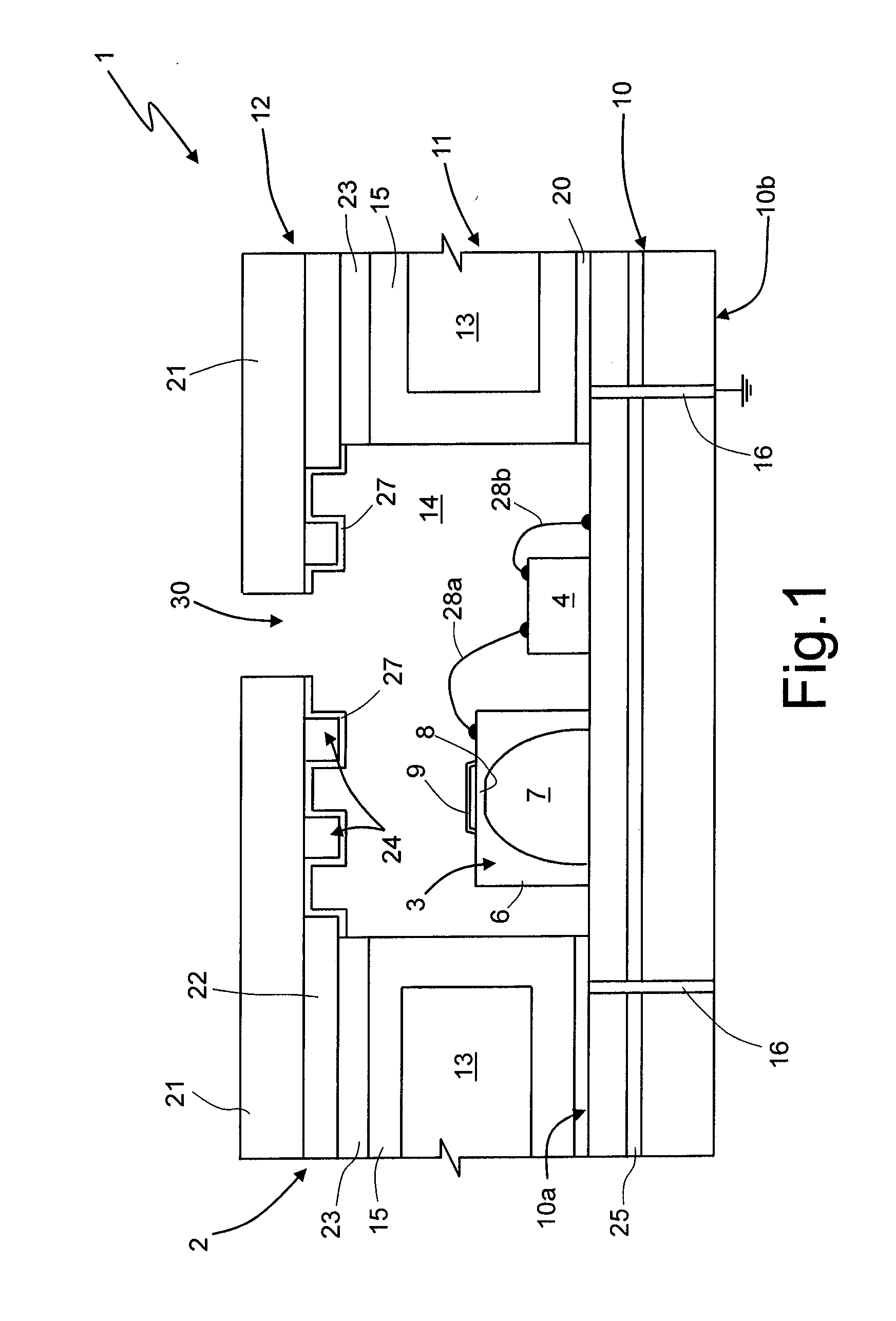
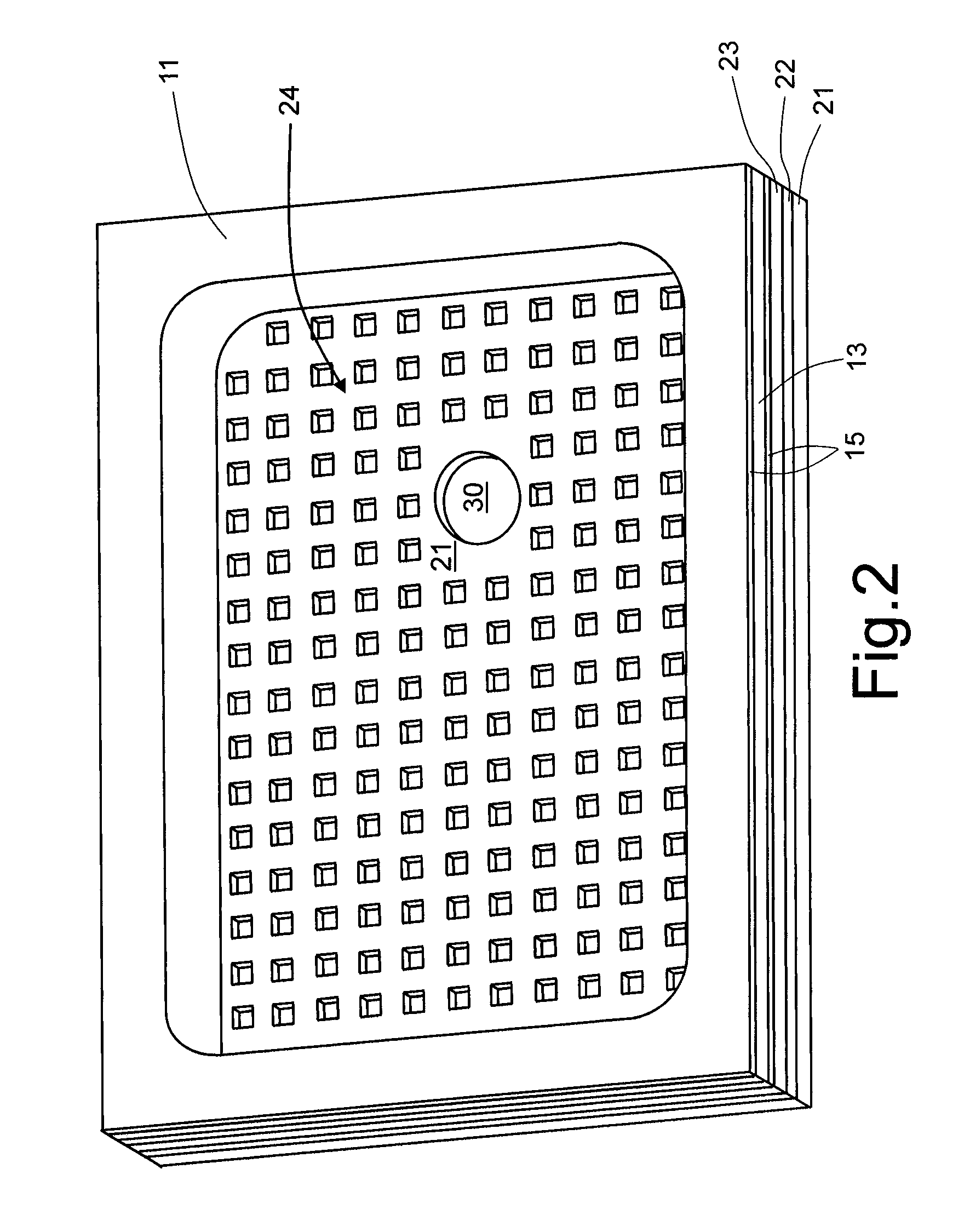
[0027]With reference to FIGS. 1 and 2, a MEMS transducer 1 of an acoustic type comprises a packaging 2 housing a microphone 3, manufactured in the MEMS technology, and an integrated circuit 4, typically an ASIC (application-specific integrated circuit), formed by a semiconductor material chip integrating the reading electronics for amplifying and treating the signal generated by the microphone 3. Hereinafter, the microphone 3 and the integrated circuit 4 are also referred to as chips 3, 4.

[0028]The microphone 3 comprises a structural layer 6 of semiconductor material, for example silicon, in which a cavity 7 is formed, for example through chemical etching from the back. A diaphragm 8 is formed in, or coupled to, the structural layer 6 and upwardly closes the cavity 7; the diaphragm 8 is flexible and, in use, undergoes deformation as a function of the pressure of the incident sound waves. A rigid plate 9 (generally known as “back-plate”) is arranged on top of the diaphragm 8 and faci...


PUM


Abstract

An encapsulated micro-electro-mechanical device, wherein a MEMS chip is encapsulated by a package formed by a first, a second, and a third substrates that are bonded together. The first substrate has a main surface bearing the MEMS chip, the second substrate is bonded to the first substrate and defines a chamber surrounding the MEMS chip, and the third substrate is bonded to the second substrate and upwardly closes the chamber. A grid or mesh structure of electrically conductive material is formed in or on the third substrate and overlies the MEMS chip; the second substrate has a conductive connection structure coating the walls of the chamber, and the first substrate incorporates an electrically conductive region, which forms, together with the conductive layer and the grid or mesh structure, a Faraday cage.

Description

BACKGROUND[0001]1. Technical Field[0002]The present disclosure regards an encapsulated micro-electro-mechanical device, in particular a MEMS acoustic transducer, such as a microphone.[0003]2. Description of the Related Art[0004]As is known, microphones built in MEMS (micro-electro-mechanical system) technology generally comprise a first chip integrating a pressure sensor and a second chip integrating an electronic circuit for processing electrical signals (read circuit). The two chips may be mounted on a support and encapsulated in a package that mechanically protects the chips, above all the microphone, which is in itself fragile and very subject to damage. Furthermore, the package may have metal structures forming Faraday cages for eliminating electromagnetic interference.[0005]Various types of package forming Faraday cages are known for integrated circuits. For example, in some solutions, the package is formed by a base, on which a support for the chips is bonded, and by a cap so...

Claims


Application Information

Patent Timeline
Patent Type & Authority Applications(United States)
IPC IPC(8): H04R1/00H01L21/02
CPCB81B7/0064B81B2201/0257B81C1/00333H01L2224/48091H01L2924/1461H01L2224/48464H01L2224/48137H01L2924/00014H01L2924/00
Inventor SHAW, MARK ANDREWCAMILLO, GIANMARCO ANTONIO
Owner STMICROELECTRONICS SRL
Why Eureka
Try Eureka