Laser welding method

a laser welding and laser beam technology, applied in welding/soldering/cutting articles, metal working devices, manufacturing tools, etc., can solve the problems of difficult to diffuse the gas emitted from the surface-treated layers, laser forming process, and inability to form desired gaps, etc., to achieve excellent quality and sputtering and internal defects

Active Publication Date: 2011-11-17
HONDA MOTOR CO LTD
View PDF7 Cites 11 Cited by
  • Summary
  • Abstract
  • Description
  • Claims
  • Application Information

AI Technical Summary

Benefits of technology

[0005]The present invention has been made in view of the above problems. It is an object of the present invention to provide a laser beam welding method which allows a gas produced from the metal of surface-treated layers of metal sheets when the metal sheets are welded using a laser beam, to be diffused regardless of the position or shape of the metal sheets or the way in which the metal sheets are clamped, so that the metal sheets can stably be welded without sputtering and internal defects, resulting in a product of excellent welding quality.
[0007]Therefore, a gas which is produced from the metal of the surface-treated layers when the metal sheets are welded is diffused regardless of the position or shape of the metal sheets or the way in which the metal sheets are clamped, so that the metal sheets can stably be welded without sputtering and internal defects, resulting in a product of excellent welding quality.
[0010]With the laser beam welding method according to the present invention, a gap or a discharge port having a desired size for diffusing a gas is formed between the stacked workpieces regardless of the position or shape of the steel sheets or the way in which the metal sheets are clamped, for diffusing a gas which is produced from the metal of the surface-treated layer when the metal sheets are welded. As a result, the pressure of the gas produced from the surface-treated layer when the metal sheets are welded with the laser beams is lowered, so that sputtering and internal defects are prevented from being caused, and the metal sheets can stably be welded with laser beams, resulting in a product of excellent quality.

Problems solved by technology

In the case where the welded region is located in the vicinity of the center of the metal sheets, it will be difficult to diffuse the gas emitted from the surface-treated layers.
However, the laser forming process is problematic in that a desired gap may not be formed due to a change in the rigidity of the metal sheets which is caused depending on the position or shape of the metal sheets or the way in which the metal sheets are clamped.

Method used


Image

  • Laser welding method
  • Laser welding method
  • Laser welding method

Examples


Embodiment Construction

[0026]Laser beam welding methods according to preferred embodiments of the present invention in relation to apparatus for carrying out the beam welding methods will be described in detail below with reference to the accompanying drawings.

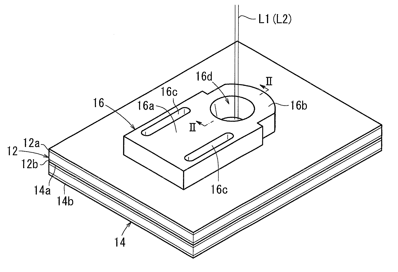
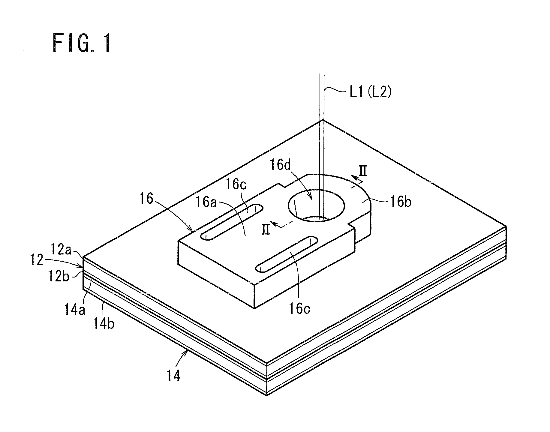
[0027]As shown in FIG. 1, a laser beam welding method according a first embodiment of the present invention uses a first workpiece 12 in the form of a first metal sheet, a second workpiece 14 in the form of a second metal sheet, and a clamping jig 16. Laser beams are applied to the first workpiece 12 in a preliminary irradiation mode and a main irradiation mode, respectively.

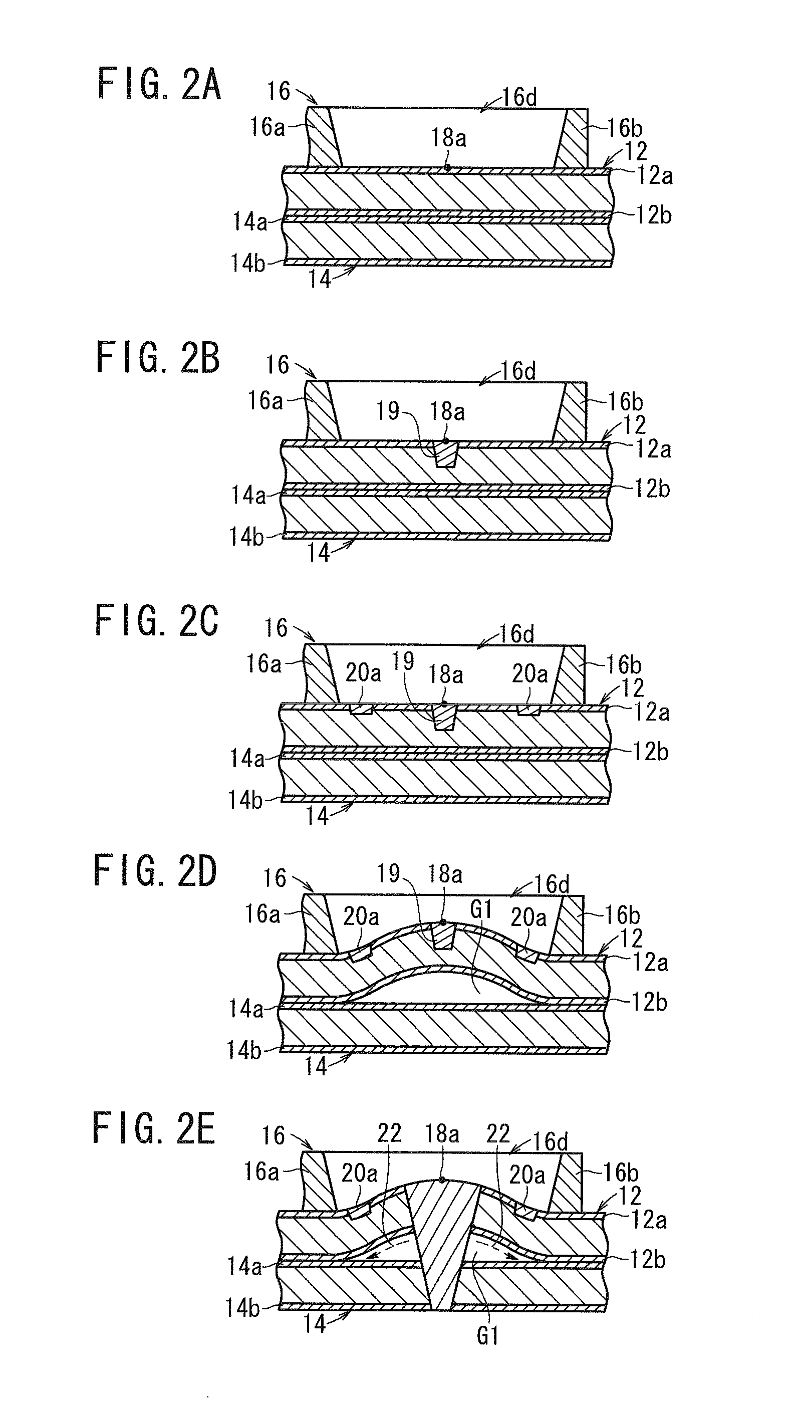
[0028]According to the first embodiment, the first workpiece 12 includes an upper surface-treated layer 12a and a lower surface-treated layer 12b, and the second workpiece 14 includes an upper surface-treated layer 14a and a lower surface-treated layer 14b. Each of the upper surface-treated layer 12a, the lower surface-treated layer 12b, the upper surface-treated layer 14a, and ...


PUM

PropertyMeasurementUnit
angleaaaaaaaaaa
angleaaaaaaaaaa
pressureaaaaaaaaaa

Abstract

The method of lap-welding of metal plates using a laser beam, wherein at least one of the metal plates is surface-treated, includes putting a metal plate on the other metal plate and forming a gap between the metal plates so that gas generated at the treated surface at the time weld can be dissipated therethrough. A surface-treated first work and a surface-treated second work are placed one on the other and clamped by means of a clamp with an opening of the clamp centered at the location on the first work to be welded. Then a laser beam is directed to the location to form a weld. The beam is then directed near the inner periphery of the opening to form a heated portion so that the heated portion deflects to form a gap through which the gas generated at the treated surface dissipates thereby reducing gas pressure.

Description

1. TECHNICAL FIELD[0001]The present invention relates to a laser beam welding method (laser welding method) for workpieces in the form of metal sheets having superposed surfaces, at least one of which is surface-treated. Specifically, the present invention relates to a laser beam welding method which is capable of reducing the influence of gas produced from a surface-treated layer in a laser beam welding process as much as possible.2. BACKGROUND ART[0002]Heretofore, surface-treated metal sheets such as galvanized steel sheets have widely been used as structural members for automotive bodies, etc. In welding such metal sheets with a laser beam, a gas is produced from the metal of the surface-treated layers while the surface-treated layers and the metal sheets are being melted. It is well known in the art that part of the melted metal sheets is blown away to cause sputtering or internal defects under the pressure of the metal gas emitted from the surface-treated layers, thereby tendin...

Claims


Application Information

Patent Timeline
Patent Type & Authority Applications(United States)
IPC IPC(8): B23K26/00B23K26/21B23K26/32
CPCB23K26/3293B23K26/246B23K26/244B23K2101/34B23K2103/08B23K26/10B23K26/20B23K26/32
Inventor KOBAYASHI, HARUHIKOOHKUBO, SATOSHIMIYASAKA, SHINICHIODA, KOJITAKAHASHI, NAOKIKAMACHI, HIDEARI
Owner HONDA MOTOR CO LTD
Why Eureka
Try Eureka