Radio frequency patch antennas for wireless communications

a radio frequency patch and wireless communication technology, applied in the field of radio frequency (rf) communications and antennas, can solve the problems of limited operating range of such access points, insufficient sensitivity for reliable communications, and the transmission itself is typically not sufficient power or sensitivity for reliable communications, and achieves high efficiency, high gain, and compact size.

Inactive Publication Date: 2011-11-17
RFTELLIGENT
View PDF3 Cites 16 Cited by
  • Summary
  • Abstract
  • Description
  • Claims
  • Application Information

AI Technical Summary

Benefits of technology

[0013]In accordance with one embodiment of the present disclosure, an antenna assembly connectible to a radio frequency (RF) front end integrated circuit is contemplated. The connection may be a feeding line with a primary conductor and a secondary conductor. The antenna assembly may include a feed port that is connectible to the feeding line, and the feed port may define a first electrically conductive element connectible to the primary conductor and a second electrically conductive element connectible to the secondary conductor. There may be a first set of inner patch elements that each has substantially identical first dimensions corresponding to a center resonant operating frequency. The inner patch elements may also define perpendicular slots of predetermined lengths. A first one of the first set of inner patch elements may be in a spaced, parallel relationship to a second one of the first set of inner patch elements. There may also be a second set of outer patch elements that each has substantially identical second dimensions. The first set of inner patch elements may be in a spaced, parallel and interposed relationship between the second set of outer patch elements. The first electrically conductive element of the feed port may be connected to the first one of the first set of inner patch elements. The second electrically conductive element of the feed port may be connected to the second one of the first set of inner patch elements. The antenna assembly may have a compact size, high gain, high efficiency, wide bandwidth and good return loss with a wide radiation pattern.

Problems solved by technology

The transceiver itself typically does not generate sufficient power or have sufficient sensitivity for reliable communications.
Accordingly, the operating range of such access points is limited and may not provide an ideal extent of network coverage.
Some extremities of a network deployment location such as room and building corners and the like may have accessibility gaps.
As the various electrical components of communications devices are densely packed, interference between the antenna and such nearby components is also a source of performance degradation.
With current antenna designs, the return loss (S11) at the edges of the operating frequency band is typically around −5 dB, leading to a reduced performance of the front end module.
This, in turn, reduces the total radiated power, the total integrated sensitivity of the transceiver, and the quality of the digital signal.
The cumulative effects of such performance degradations include shorter communication link distances, increased data transfer times, and a host of other problems attendant thereto.

Method used


Image

  • Radio frequency patch antennas for wireless communications
  • Radio frequency patch antennas for wireless communications
  • Radio frequency patch antennas for wireless communications

Examples


Embodiment Construction

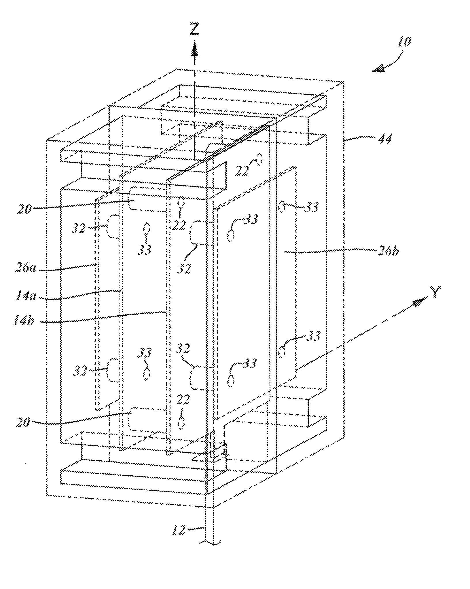
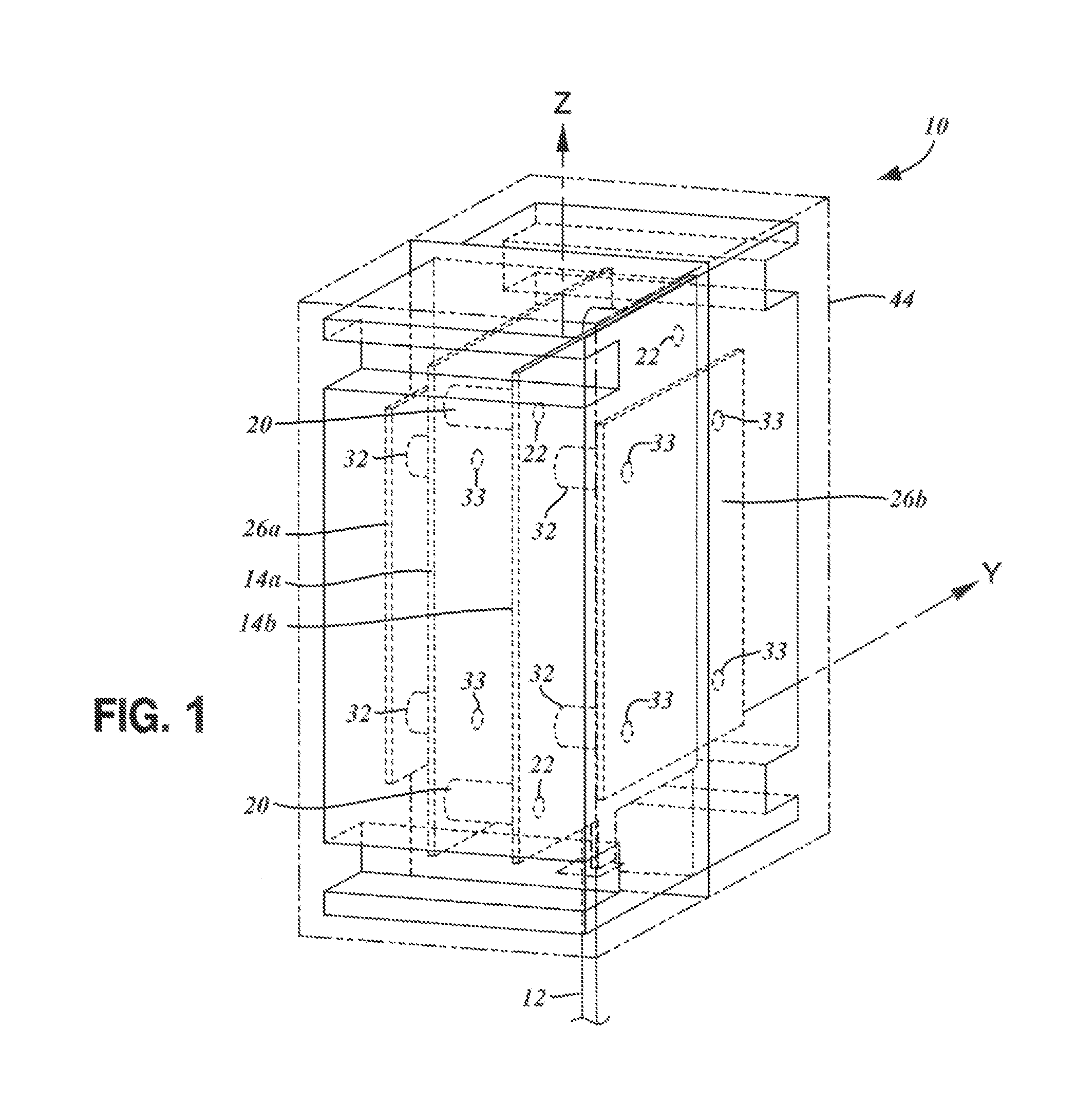
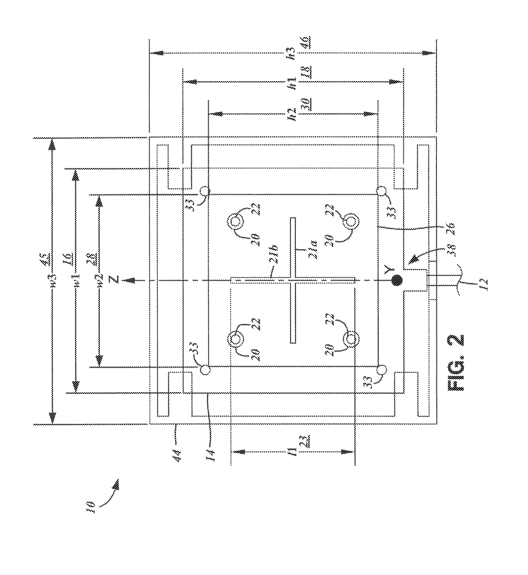
[0039]The present disclosure contemplates various embodiments of patch antennas, cross-polarized patch antennas and patch antenna arrays with high gain, wide bandwidth, high efficiency, good return loss, and a broad radiation pattern. The detailed description set forth below in connection with the appended drawings is intended as a description of the presently preferred embodiment of the invention, and is not intended to represent the only form in which the present invention may be developed or utilized. The description sets forth the functions of the invention in connection with the illustrated embodiment. It is to be understood, however, that the same or equivalent functions may be accomplished by different embodiments that are also intended to be encompassed within the scope of the invention. It is further understood that the use of relational terms such as first and second, primary and secondary, and the like are used solely to distinguish one from another entity without necessa...


PUM


Abstract

An antenna assembly connectible to a radio frequency (RF) front end integrated circuit is disclosed. The antenna assembly includes a feed port connectible to a feeding line. There is a set of inner patch elements each having substantially identical first dimensions corresponding to a center resonant operating frequency, and also define perpendicular slots of predetermined lengths. The inner patch elements are in a spaced, parallel relationship. A set of outer patch elements each has substantially identical second dimensions. The inner patch elements are in a spaced, parallel and interposed relationship between the set of outer patch elements. A first electrically conductive element of the feed port is connected to a first one of the inner patch elements, and a second electrically conductive element of the feed is connected to a second one of the inner patch elements.

Description

CROSS-REFERENCE TO RELATED APPLICATIONS[0001]This application relates to and claims the benefit of U.S. Provisional Application No. 61 / 334,132, filed May 12, 2010 and entitled “CROSS-POLARIZED HIGH GAIN AND WIDEBAND PATCH ANTENNA FOR WLAN MIMO APPLICATIONS,” U.S. Provisional Application No. 61 / 334,026 filed May 12, 2010 and entitled “11 dBi HIGH GAIN WIDEBAND PATCH ANTENNA ARRAY FOR WLAN APPLICATIONS” and U.S. Provisional Application No. 61 / 334,128 filed May 12, 2010 and entitled “HIGH GAIN AND BROAD RADIATION PATTERN ANTENNA FOR WLAN APPLICATIONS,” each of which are wholly incorporated by reference herein.STATEMENT RE: FEDERALLY SPONSORED RESEARCH / DEVELOPMENT[0002]Not ApplicableBACKGROUND[0003]1. Technical Field[0004]The present disclosure relates generally to radio frequency (RF) communications and antennas, and more particularly to patch antennas, cross-polarized patch antennas, and patch antenna arrays for use with RF integrated circuits in industrial-scientific-medical (ISM) ba...

Claims


Application Information

Patent Timeline
Patent Type & Authority Applications(United States)
IPC IPC(8): H01Q9/04H01Q1/50H01Q1/42
CPCH01Q1/2291H01Q1/42H01Q5/378H01Q9/0435H01Q21/08H01Q9/0414
Inventor HE, ZIMINGPENG, PINGGORBACHOV, OLEKSANDR
Owner RFTELLIGENT
Why Eureka
Try Eureka