Eureka AIR delivers breakthrough ideas for toughest innovation challenges, trusted by R&D personnel around the world.

Heat sink and cooling method for LED lighting and other applications

Inactive Publication Date: 2011-11-17
CONTENT RONALD A +1
View PDF3 Cites 7 Cited by
  • Summary
  • Abstract
  • Description
  • Claims
  • Application Information

AI Technical Summary

Problems solved by technology

For certain applications, such clean rooms in the semiconductor industry, re- lamping may be quite expensive costing millions, especially in view of the fact that production must typically be stopped throughout the process.
For such applications, long life and reliability are critical.
However, LEDs powerful enough for room lighting are relatively expensive and require more precise current and heat management than compact fluorescent lamp sources of comparable output.
However, these approaches have been costly in the use of aluminum or metal core circuit boards and have been only minimally effective.

Method used


Image

  • Heat sink and cooling method for LED lighting and other applications
  • Heat sink and cooling method for LED lighting and other applications
  • Heat sink and cooling method for LED lighting and other applications

Examples


Embodiment Construction

[0033]Illustrative embodiments and exemplary applications will now be described with reference to the accompanying drawings to disclose the advantageous teachings of the present invention.

[0034]While the present invention is described herein with reference to illustrative embodiments for particular applications, it should be understood that the invention is not limited thereto. Those having ordinary skill in the art and access to the teachings provided herein will recognize additional modifications, applications, and embodiments within the scope thereof and additional fields in which the present invention would be of significant utility.

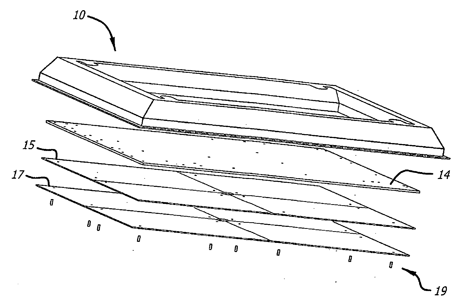
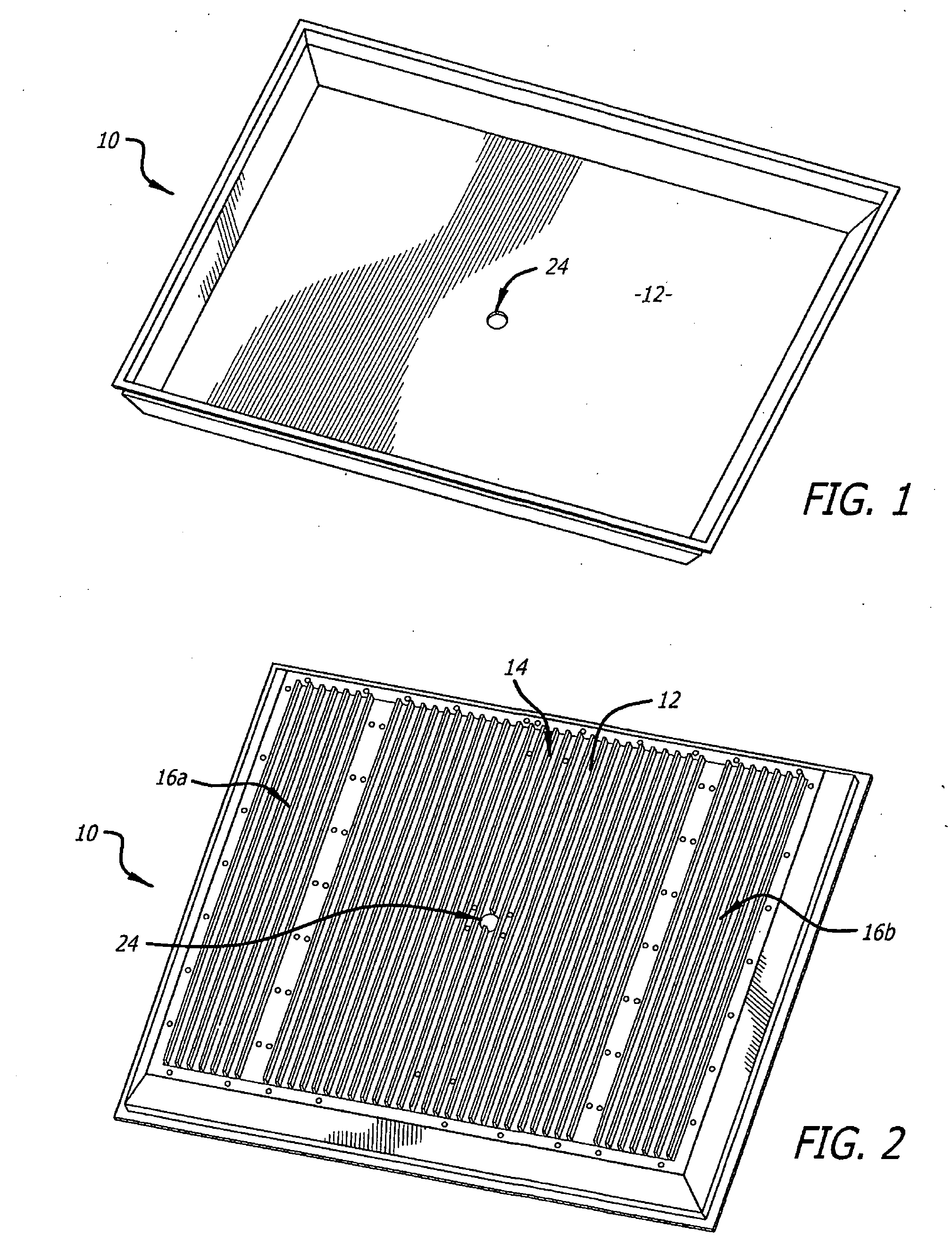
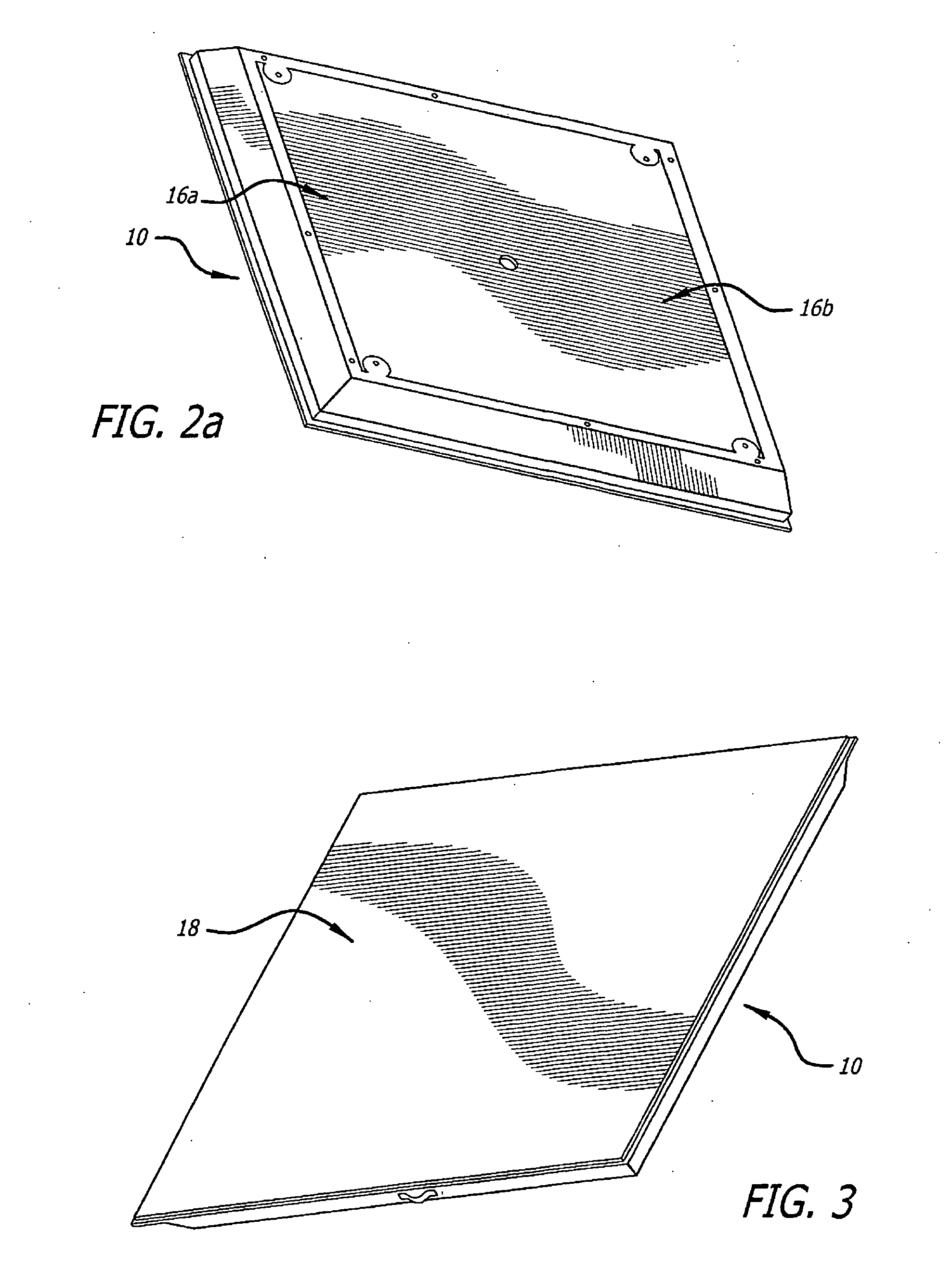
[0035]The present invention is directed to lighting apparatus using a troffer assembly, heat sinks and methods of manufacturing lighting apparatus and heat sinks. In embodiments of the present invention, the lighting apparatus is designed as a light emitting diode (LED) luminaire that can replace traditional fluorescent-based troffers that are often ...


PUM

PropertyMeasurementUnit
Lengthaaaaaaaaaa
Sizeaaaaaaaaaa
Shapeaaaaaaaaaa

Abstract

An inventive heat sink adapted for use with light emitting diode luminaires and other applications comprising: a first layer of carbon graphite in thermal communication with a source of heat and a second layer of aluminum in thermal communication with said first layer. Also disclosed is an inventive troffer including a frame; a printed circuit board mounted within the frame; an array of light emitting diodes mounted on the printed circuit board; a heat sink mounted in parallel with the printed circuit board; and a thermal interface layer disposed between the heat sink and the printed circuit board. In yet another embodiment, the inventive troffer assembly includes plural modules mounted within the frame, each module including: a printed circuit board mounted within the frame; an array of light emitting diodes mounted on the printed circuit board; a heat sink mounted in parallel with the printed circuit board; and a thermal interface layer disposed between the heat sink and the printed circuit board.

Description

REFERENCE TO RELATED APPLICATION[0001]This is a nonprovisional application claiming priority from a provisional application entitled Lighting Apparatus, Heat Sinks and Methods of Manufacturing filed May 12, 2010, Ser. No. 61 / 334,173, (Attorney Docket No. 1011-003).BACKGROUND OF THE INVENTION[0002]1. Field of the Invention[0003]The present invention relates to lighting systems. More specifically, the present invention relates to heat sinks for light emitting diode based lighting systems.[0004]2. Description of the Related Art[0005]As noted in Wikipedia at http: / / en.wikipedia.org / wiki / Light-emitting diode a light-emitting diode (LED) is a semiconductor light source. LEDs are used as indicator lamps in many devices and are increasingly used for general lighting applications. Introduced as a practical electronic component in 1962, early LEDs emitted low-intensity red light, but modern versions are available across the visible, ultraviolet and infrared wavelengths, with very high brightn...

Claims


Application Information

Patent Timeline
IPC IPC(8): F21S4/00F28F7/00B21D53/02F21S8/06
CPCF21Y2105/001Y10T29/4935F21V29/89F21V29/86F21Y2105/10F21Y2115/10
Inventor CONTENT, RONALD A.SWARIS, JAGATH A.
Owner CONTENT RONALD A
Why Eureka
Eureka Blog
Learn More