Irrigated finned ablation head

a technology which is applied in the field of irrigated fins and ablation heads, can solve the problems of blood clot formation and persisting implementation of irrigated ablation heads

Active Publication Date: 2011-11-17
ST JUDE MEDICAL INT HLDG SARL
View PDF38 Cites 54 Cited by
  • Summary
  • Abstract
  • Description
  • Claims
  • Application Information

AI Technical Summary

Benefits of technology

[0008]In various embodiments of the invention, a finned ablation head that generates non-uniform velocity / flow profile is disclosed wherein the flow and the attendant convective cooling is actually greater near the proximal portion of the irrigated ablation head than at the distal extremity. While cooling flow is still provided to the distal extremity of the finned ablation head, various embodiments of the design of the fins also take advantage of the conduction of heat away from the distal extremity to the higher convective cooling regions at the proximal end of the irrigated finned ablation head.

Problems solved by technology

Despite such designs, problems persist in the implementation of irrigated ablation heads.
Such problems include coagulation of blood in recirculation zones about the ablation head that can lead to the formation of blood clots.

Method used


Image

  • Irrigated finned ablation head
  • Irrigated finned ablation head
  • Irrigated finned ablation head

Examples


Embodiment Construction

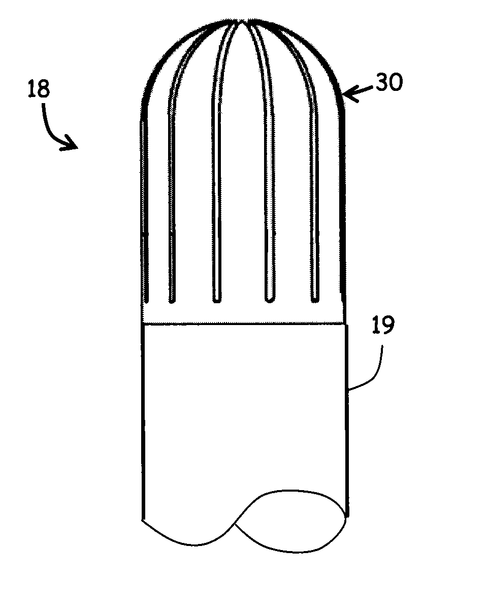
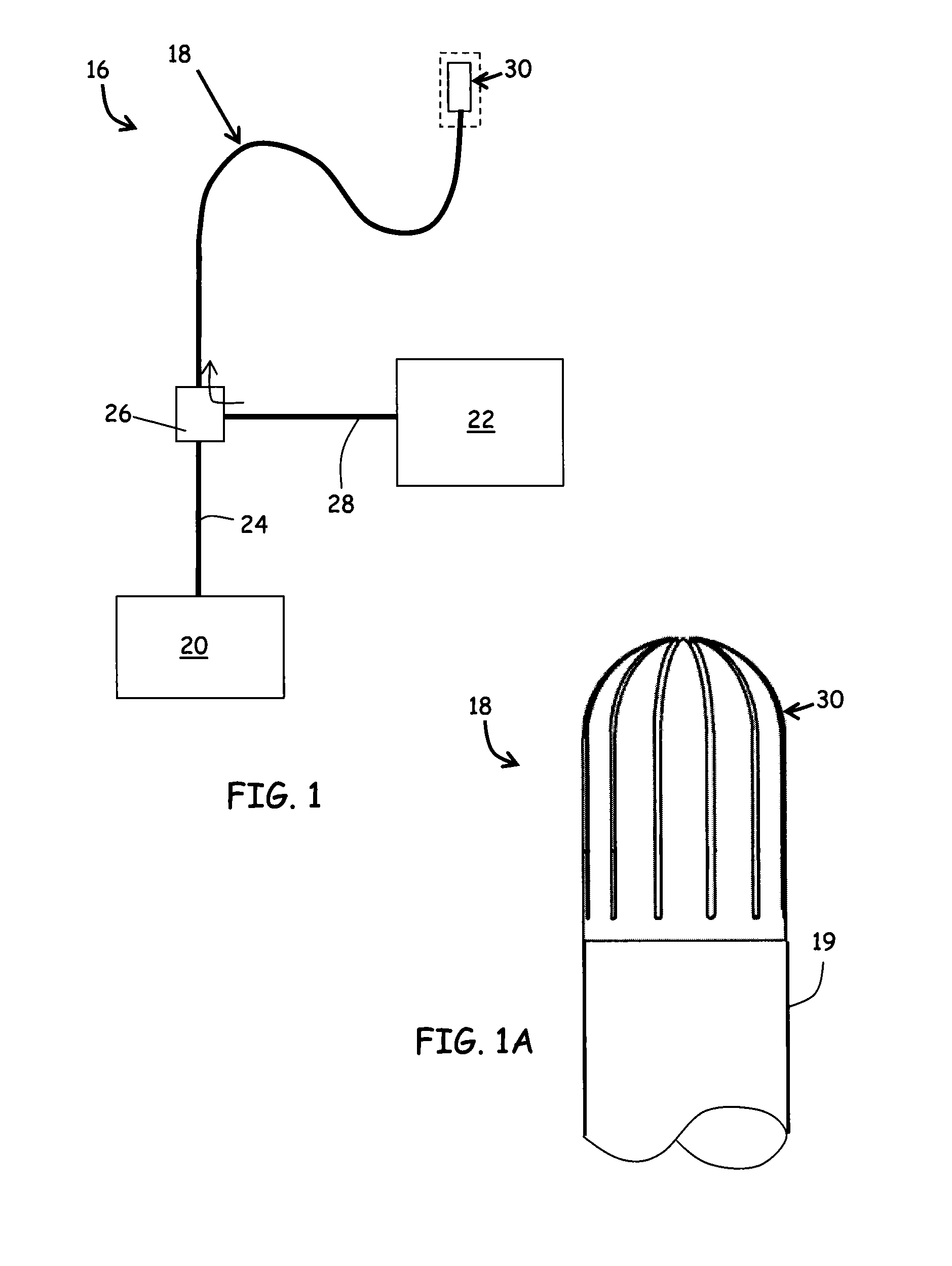
[0044]Referring to FIG. 1, an ablation catheter system 16 having a catheter 18 having an elongated, flexible shaft 19 and an irrigated finned ablation head 30 positioned at one end of the flexible shaft 19. Herein, several embodiments of the irrigated finned ablation head 30 are presented, designated specifically by letter suffix (e.g., “30a”) and referred to collectively by numerical reference 30. The catheter system 16 can further comprise a power supply 20 for powering the irrigated finned ablation head 30 and an irrigation supply 22 for providing fluids to the irrigated finned ablation head 30. In an embodiment of the invention, the catheter system 16 can further comprise a thermocouple lead extending from proximate to the irrigated finned ablation head 30 through the other end of the flexible shaft 19. The elongated catheter 18 defines an internal lumen for receiving a power supply line 24 linking the irrigated finned ablation head 30 to the power supply 20. Similarly, the inte...


PUM


Abstract

An irrigated finned ablation head that provides enhanced cooling. The irrigated finned ablation head comprises a plurality of radial fins that are distributed about a central axis and that extend axially from a common base. The plurality of fins are arranged to define a central passageway along the central axis, as well as a plurality of slots therebetween, the slots extending in an axial direction along the irrigated finned ablation head. In one embodiment, the central passageway extends through the irrigated finned ablation head, defining an opening at the distal extremity, with the slots extending from the base to the opening. In another embodiment, the irrigated finned ablation head includes a cap portion at a distal portion that is common to all the radial fins, so that the slots are terminated at the distal portion of the irrigated finned ablation head. The radial flow distribution along the central axis can be tailored by the configuration of the central passageway.

Description

RELATED APPLICATIONS[0001]This application claims the benefit of U.S. Provisional Application 61 / 333,045 entitled “Finned Ablation Head,” filed May 10, 2010, the entire contents of which are hereby incorporated by reference herein.FIELD OF THE DISCLOSURE[0002]The present invention relates to methods and devices for performing minimally invasive ablative procedures within mammalian bodies. Specifically, the present invention relates to methods and devices that implement an irrigated finned ablation head for enhanced cooling features for temperature control of irrigated ablation heads and prevention of blood coagulation and other complications resulting ablative procedures.BACKGROUND OF THE DISCLOSURE[0003]An ablation catheter is a catheter having an end effector, such as a radio-frequency (RF) ablation head, designed to deliver energy to a target tissue for the purpose of forming a lesion on the target tissue. Catheter-based ablation therapy is performed by accessing the target tissu...

Claims


Application Information

Patent Timeline
Patent Type & Authority Applications(United States)
IPC IPC(8): A61B18/18
CPCA61B18/1492A61B2218/002A61B2018/00029A61B2018/00011
Inventor LEO, GIOVANNIAEBY, NICOLAS
Owner ST JUDE MEDICAL INT HLDG SARL
Why Eureka
Try Eureka