
Self Powered Cooling

a self-powered cooling and cooling system technology, applied in nuclear power plants, greenhouse gas reduction, nuclear engineering, etc., can solve the problems of failure or disruption of the operation of cooling systems, stoppage of main process with adverse and undesirable consequences, and meltdown with catastrophic consequences, so as to prevent material damage and be immune from external power outages

Inactive Publication Date: 2011-11-24
EFTEKHARZADEH SHAHRIAR
View PDF13 Cites 23 Cited by
  • Summary
  • Abstract
  • Description
  • Claims
  • Application Information

AI Technical Summary

Benefits of technology

The present invention provides an answer to the above stated need by using the thermal energy of the spent fuel rods as the main source of power for the operation of the nuclear power plant cooling system, making it an internally powered cooling system that does not require any external source of electrical power for its intended operation, and therefore cannot be disrupted by external power outages. The cooling system operation will continue without interruption for as long as there is adequate thermal energy in the spent fuel rods, which is in the order of several years after removal from the reactors and transfer to the spent fuel rod storage ponds. The invention may also be used in other industries by using the thermal energy of the process waste heat as the main source of power for the operation of the plant cooling system. For such applications the cooling system is designed to continue operation until the reduction in the waste heat due to process shut down and continued cooling reaches a level where active cooling is no longer required to ensure safety or to prevent material damage. Therefore, the present invention makes the cooling systems in both nuclear power generation and in other industries immune from external power outage.
The difference between the present invention and previous inventions that also work by recovery and conversion of process thermal energy and waste heat is the object of the present invention, which is to use the recovered thermal energy for powering the cooling system of the process itself i.e. to realize power redundancy for the process cooling system. This is fundamentally different from the recovery and conversion of process waste heat to improve process efficiency, for which there is ample precedence. The fact that the present invention uses the process waste heat for thermal energy input means that it also improves process efficiency, but that is not an object of this invention.

Problems solved by technology

Failures or disruptions in the operation of cooling systems cannot be tolerated as it results in the stoppage of the main process with adverse and undesirable consequences.
In the absence of adequate cooling, the fuel rods can heat up to extremely high temperatures and cause meltdown with catastrophic consequences.
Therefore, redundant power for the cooling system of nuclear power plants is critically important because failure of the cooling system can have catastrophic consequences.
However, the current power redundancy arrangement for nuclear power plants has proven to be fatally inadequate.
This is a fact that was tragically demonstrated by the Fukushima Daiichi nuclear power plant cooling system failure in Japan following the 9.0 magnitude Tohoku earthquake and tsunami on 11 Mar. 2011.
The earthquake prompted the automatic shut down of the nuclear power plant, which cut off the main power supply to the cooling system.
However, the Tsunami that followed caused the entire plant to flood, including the backup emergency generators and electrical switchgear.
Also, the connection to the electrical grid was broken as the Tsunami destroyed the power lines.
The backup batteries were only adequate for a few hours of cooling system operation.
All power for cooling was lost and reactors started to overheat and meltdown owing to the natural decay of the fission products in the fuel rods.
The water in the spent fuel storage pond started to overhead and to generate hydrogen which subsequently exploded with catastrophic consequences.
The failure has been attributed to the inability to furnish a truly redundant and fail-safe power supply source for the cooling system.

Method used


Image

  • Self Powered Cooling
  • Self Powered Cooling
  • Self Powered Cooling

Examples


Embodiment Construction

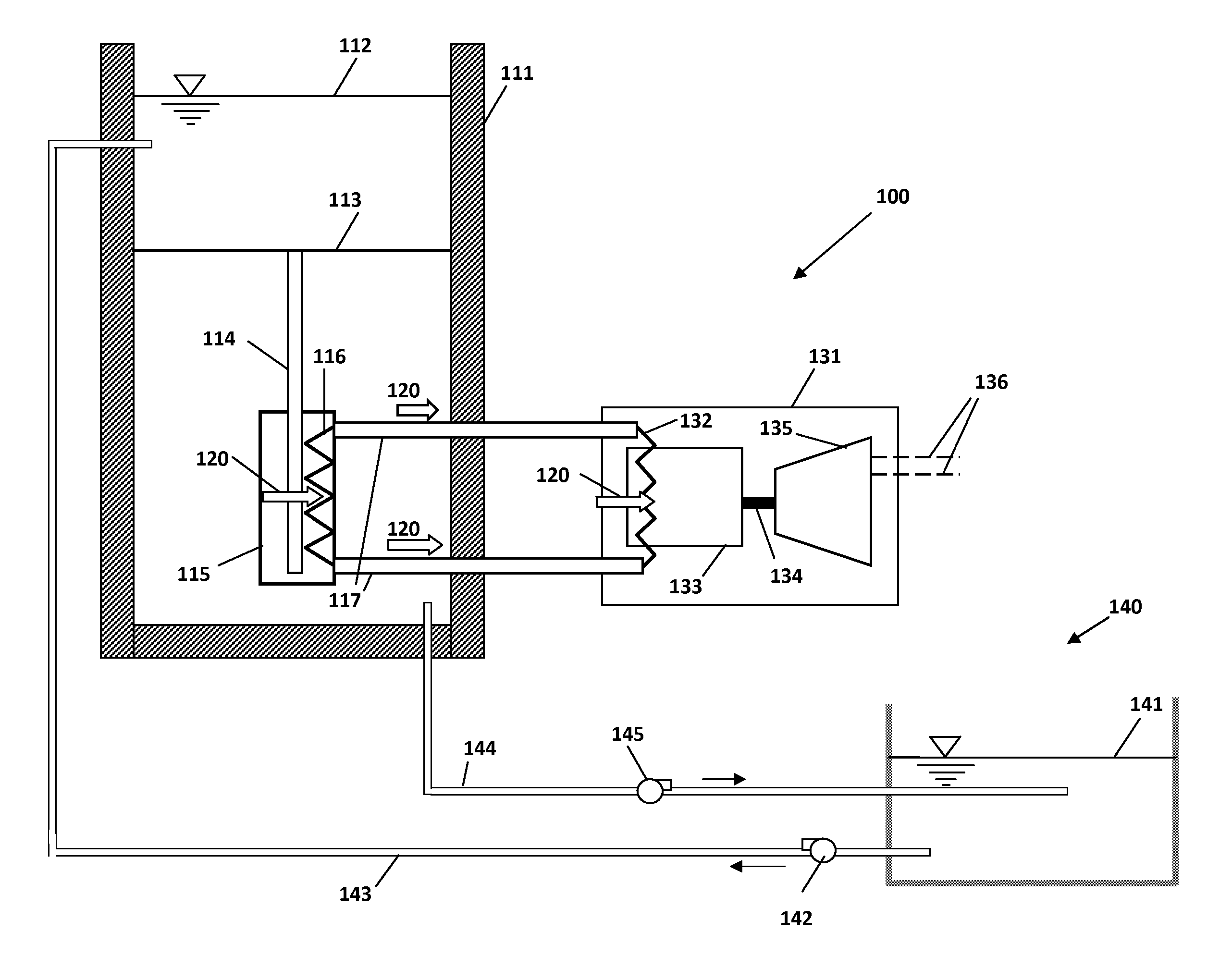
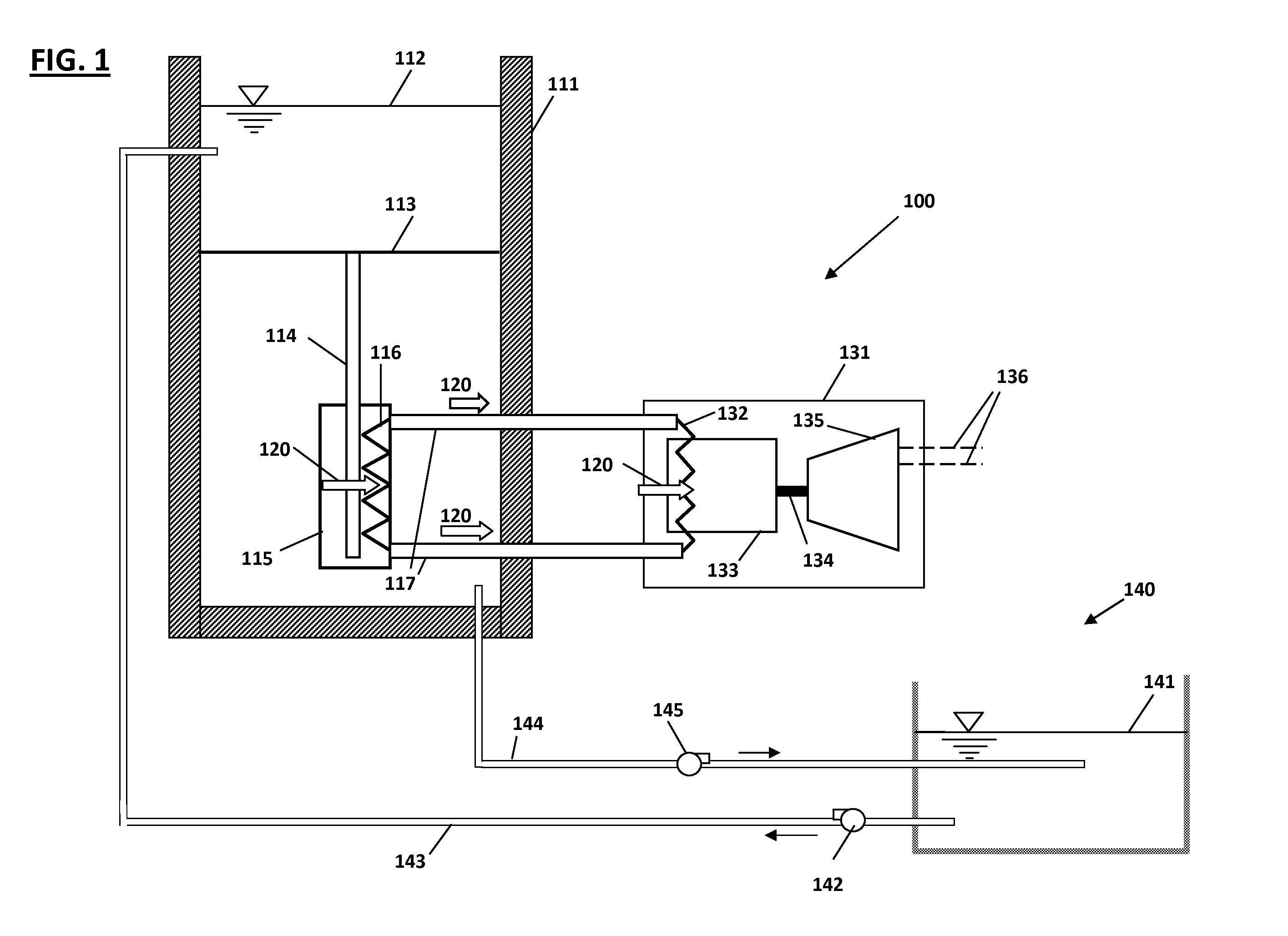
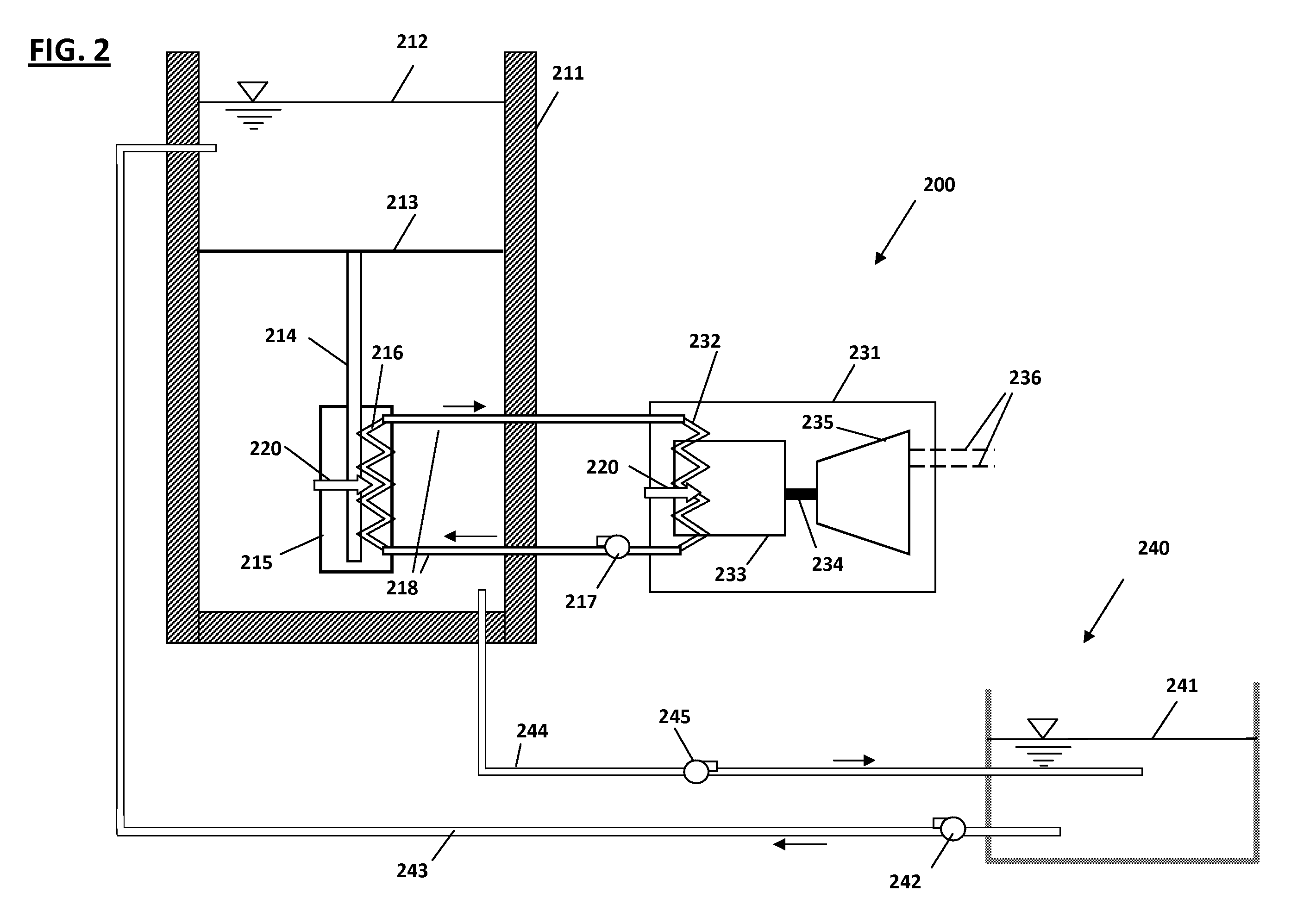
Referring first to FIG. 1, there is shown an apparatus 100 that harnesses the thermal energy 120 of the spent fuel rod 114 to power the nuclear power plant cooling system 140, according to one embodiment of the invention. Heat exchanger unit 115 is accumulates the thermal energy 120 of the spent fuel rods 114 held by support 113 inside the spent fuel rod storage pond 111 by controlled shielding of the spent fuel rods 114 from the surrounding cooling water 112 so as to achieve a pre-determined elevated temperature inside the heat exchanger 115. Internal element 116 transfers the thermal energy 120 to heat conductors 117 which convey it to the electrical power generation unit 131 by heat conduction. The latter consists of a heat engine such as a Sterling Engine 133, which receives the thermal energy 120 via element 132 and converts it to mechanical energy that drives the electrical generator 135 via transmission system 134. Electricity generated by unit 131 is transmitted via electric...


PUM


Abstract

An apparatus that harnesses the thermal energy of spent fuel rods in nuclear power plants to power the cooling system of the nuclear power plant particularly the cooling for the spent fuel rod storage ponds and the main reactors. The apparatus is comprised of a heat exchanger unit that accumulates the thermal energy of the spent fuel rods, a heat conveyance system that conveys the thermal energy of the spent fuel rods, and a heat engine that receives its thermal energy input from the spent fuel rods and produces mechanical power that runs an electrical generator which powers the cooling system of the nuclear power plant, particularly the controls and pumps that cool the spent fuel rod storage ponds and the main reactors. The apparatus provides a redundant power source and makes the cooling system of nuclear power plants independent of externally supplied electrical power and thereby resolves a key redundancy and safety concern with nuclear power generation. The apparatus also has application to other industries.

Description

FIELD OF THE INVENTIONThe present invention relates to industrial cooling systems, and more specifically to improvements thereto for powering such systems with a redundant power source that is not subject to outage. Specifically, the present invention harnesses the thermal energy of spent fuel rods in nuclear power plants to power the spent fuel rod storage ponds and reactors. The present invention may also be used in other industries to harness the thermal energy of process waste heat to power the process cooling system.BACKGROUND OF THE INVENTIONCooling is the conveyance and disposal of the waste heat generated in any process where thermal energy is converted to useful work. It is a fundamental requirement without which the process cannot be sustained. Most processes used in everyday modern life, such as in power generation, manufacturing, petrochemicals, transportation, processing, construction, etc., rely on active cooling systems that require power to operate. Power is required...

Claims


Application Information

Patent Timeline
Patent Type & Authority Applications(United States)
IPC IPC(8): G21D5/00
CPCY02E30/40G21D1/02Y02E30/00Y02E30/30
Inventor EFTEKHARZADEH, SHAHRIAR
Owner EFTEKHARZADEH SHAHRIAR
Learn More