Heat dissipation system with hygroscopic working fluid

a working fluid and heat dissipation system technology, applied in the direction of heating types, lighting and heating apparatus, domestic cooling apparatus, etc., can solve the problems of poor air cooling process efficiency, few opportunities for once-through cooling in the future, and inferior cooling of air

Inactive Publication Date: 2011-11-24
ENERGY & ENVIRONMENTAL RES CENT FOUNDATIO
View PDF8 Cites 24 Cited by
  • Summary
  • Abstract
  • Description
  • Claims
  • Application Information

AI Technical Summary

Problems solved by technology

However, few of these opportunities for once-through cooling are expected to be available in the future because of competition for water sources and recognition of their impact on the environment.
These technologies are used routinely in industry, but each one has distinct drawbacks.
In the sensible cooling case, air is an inferior coolant compared to liquids, and the resulting efficiency of air-cooled processes can be poor.
In addition to larger surface area requirements, air-cooled heat exchangers approach the ambient dry-bulb temperature, which can vary 30° to 40° F. over the course of a day and can hinder cooling capacity during the hottest hours of the day.
Choosing the lowest initial cost option can have negative energy consumption implications for the life of the system.
The key drawback of this approach is the associated water consumption, which in many areas is becoming a limiting resource.
Obtaining sufficient water rights for wet cooling system operation delays plant permitting, limits site selection, and creates a highly visible vulnerability for opponents of new development.
These systems can use less water compared to complete latent cooling, but the performance benefit is directly related to the amount of water-based augmentation, so these systems do not solve the underlying issue of water consumption.
Sensible cooling with air is costly because of the vast heat exchange surface area required and because its heat-transfer performance is handicapped during the hottest ambient temperatures.
Latent or evaporative cooling has preferred cooling performance, but it consumes large quantities of water which is a limited resource in some locations.

Method used


Image

  • Heat dissipation system with hygroscopic working fluid
  • Heat dissipation system with hygroscopic working fluid
  • Heat dissipation system with hygroscopic working fluid

Examples


Embodiment Construction

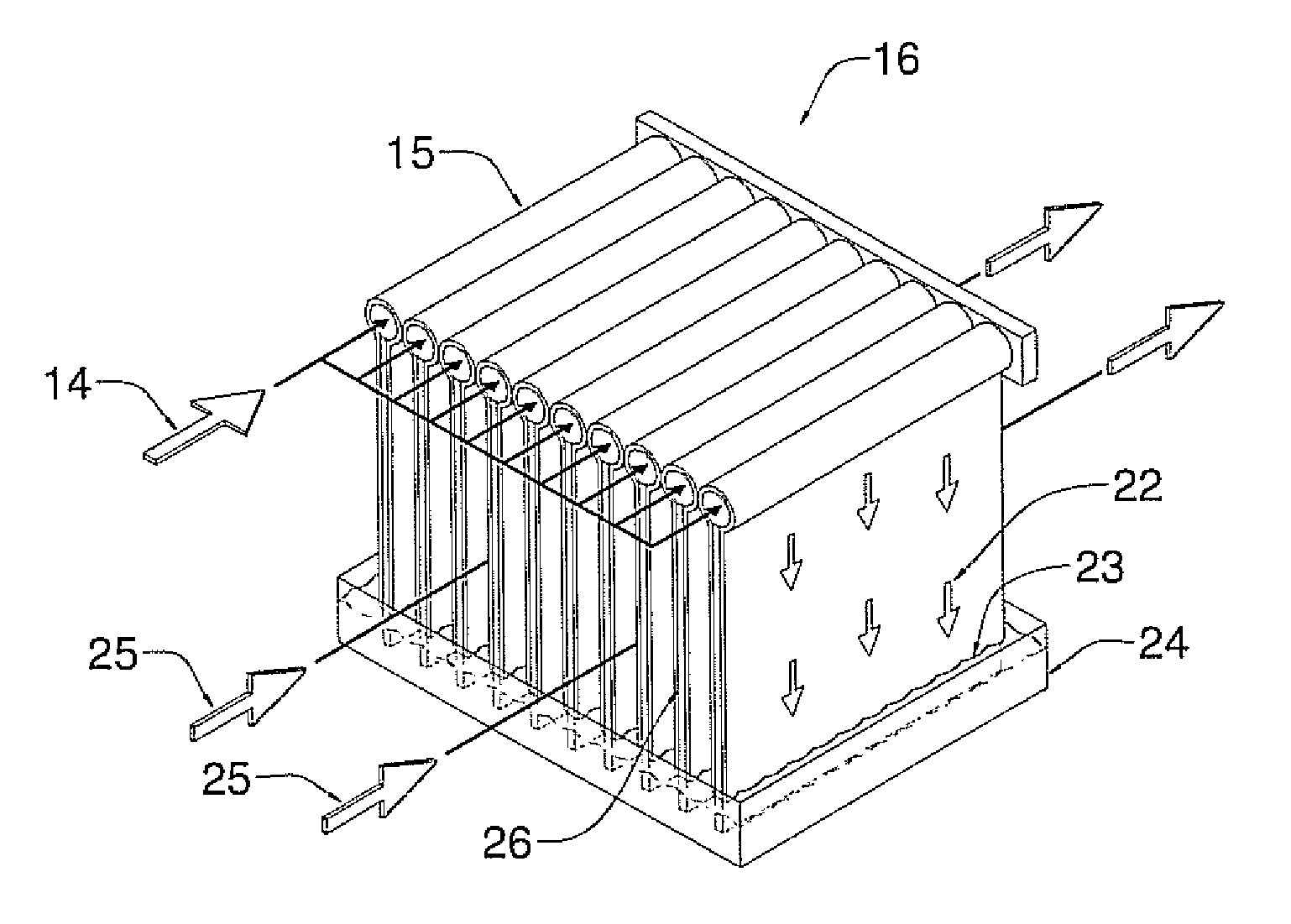
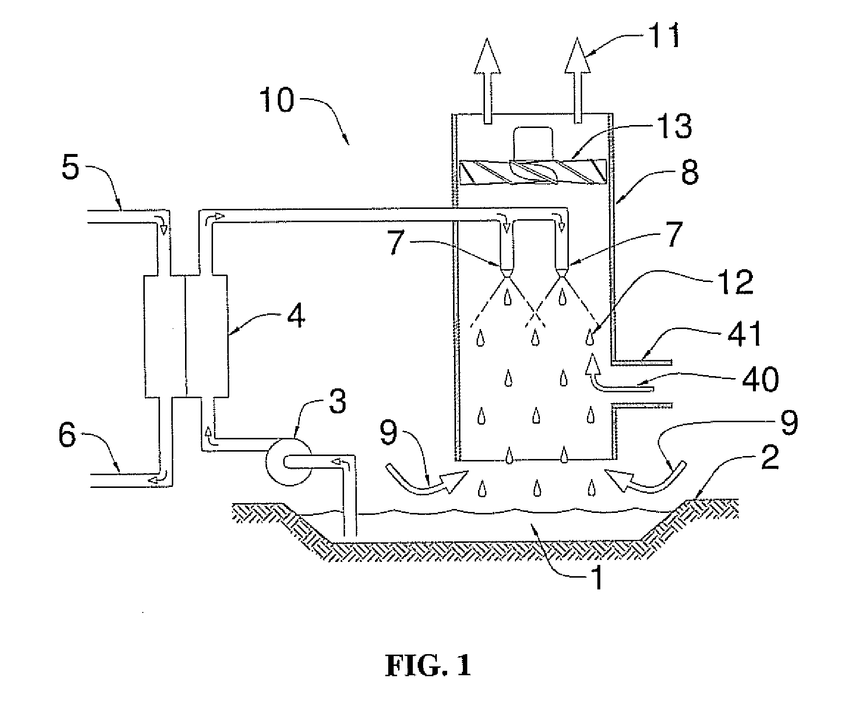
[0021]The heat dissipation system described herein circulates a hygroscopic working fluid to transfer heat from a process requiring cooling directly to the ambient air. The hygroscopic fluid is in liquid phase at conditions in which it is at thermal and vapor pressure equilibrium with the expected local ambient conditions. The fluid is composed of a solution of a hygroscopic substance and water. In one embodiment, the hygroscopic substance itself should have a very low vapor pressure compared to water in order to prevent significant loss of the hygroscopic component during cycle operation. The hygroscopic component can be a pure substance or a mixture of substances selected from compounds known to attract moisture vapor and form liquid solutions with water that have reduced water vapor pressures. The hygroscopic component includes all materials currently employed for desiccation operations or dehumidifying operations including hygroscopic inorganic salts, such as LiCl, LiBr, CaCl2, ...


PUM


Abstract

A system and method for transferring heat from a process source and dissipating it to the ambient atmosphere. The system uses a low-volatility, hygroscopic working fluid to reject thermal energy directly to ambient air. Direct-contact heat exchange allows for the creation of large interfacial surface areas for effective heat transfer. Heat transfer is further enhanced by water vapor pressure gradients present between the equilibrium moisture content of the working fluid and the ambient air. Cyclic absorption and evaporation of atmospheric moisture dampens variations in cooling capacity because of ambient temperature changes. The low-volatility and hygroscopic nature of the working fluid prevents complete evaporation of the fluid and a net consumption of water.

Description

CROSS-REFERENCE TO RELATED APPLICATIONS[0001]This application claims priority of U.S. Provisional Patent Application Ser. No. 61 / 345,864 filed May 18, 2010, which is incorporated herein in its entirety by reference.STATEMENT REGARDING FEDERALLY SPONSORED RESEARCH OR DEVELOPMENT[0002]This invention was made with government support under Cooperative Agreement No. DE-FC26-08NT43291 entitled “EERC-DOE Joint Program on Research and Development for Fossil Energy-Related Resources,” awarded by the U.S. Department of Energy (DOE). The government has certain rights in the invention.FIELD OF THE INVENTION[0003]This invention relates to the dissipation of degraded thermal energy to ambient air.BACKGROUND OF THE INVENTION[0004]Cooling and thermal energy dissipation are universal tasks in industry. Common heat rejection processes include steam condensation in thermoelectric power plants, refrigerant condensation in air-conditioning and refrigeration equipment, and process cooling during chemical...

Claims


Application Information

Patent Timeline
Patent Type & Authority Applications(United States)
IPC IPC(8): F25D17/06
CPCF25D17/06F24F3/1417F24F3/147
Inventor MARTIN, CHRISTOPHER L.
Owner ENERGY & ENVIRONMENTAL RES CENT FOUNDATIO
Why Eureka
Try Eureka