Fabricated tube for an evaporator

Inactive Publication Date: 2011-11-24
MAHLE INT GMBH
View PDF6 Cites 11 Cited by
  • Summary
  • Abstract
  • Description
  • Claims
  • Application Information

AI Technical Summary

Benefits of technology

[0015]Folded evaporator tube having the above critical parameters provide evaporators with improved heat transfer performance, reduced ref

Problems solved by technology

However, the extrusion process is known to be expensive because of the need to frequently replace the extrusion die in order to maintain the desired dimensions of the intricate geometric features.
Extruded tubes are also prone to corrosion attacks from road salt and acidic rain and require extensive co

Method used


Image

  • Fabricated tube for an evaporator
  • Fabricated tube for an evaporator
  • Fabricated tube for an evaporator

Examples


Example

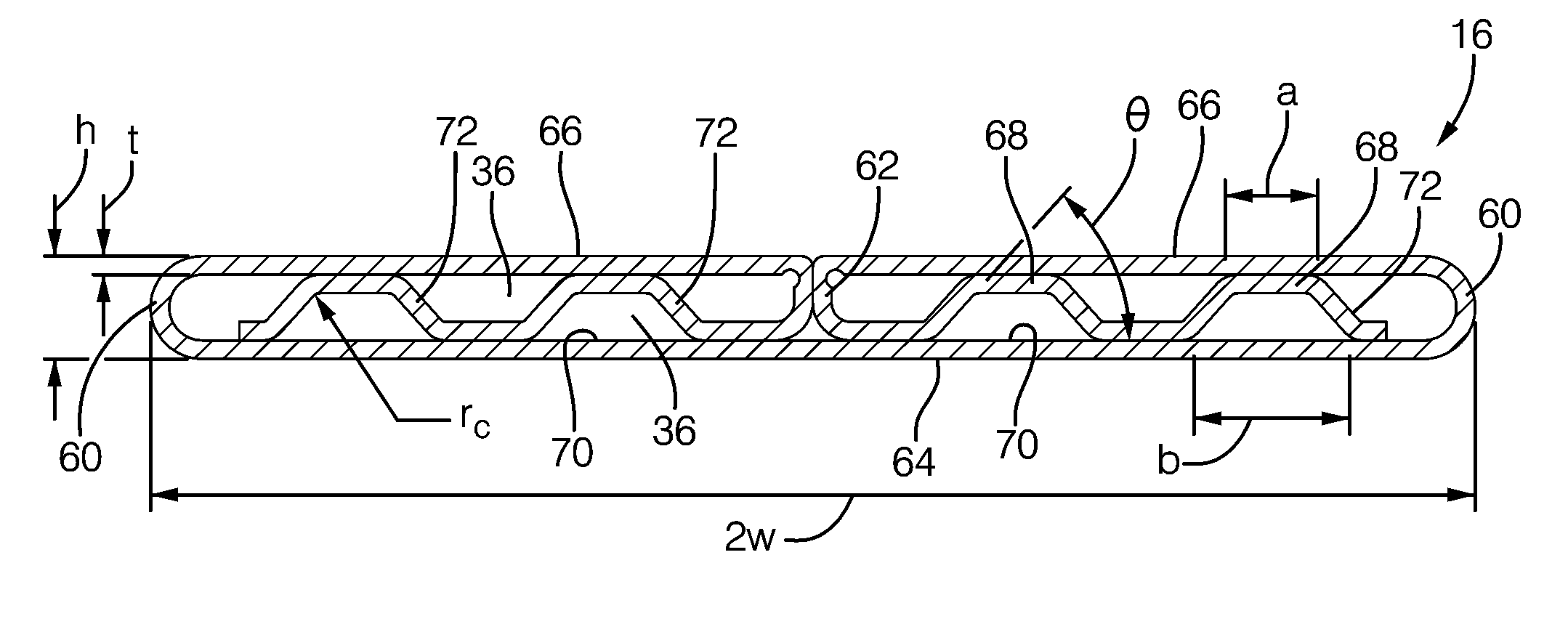
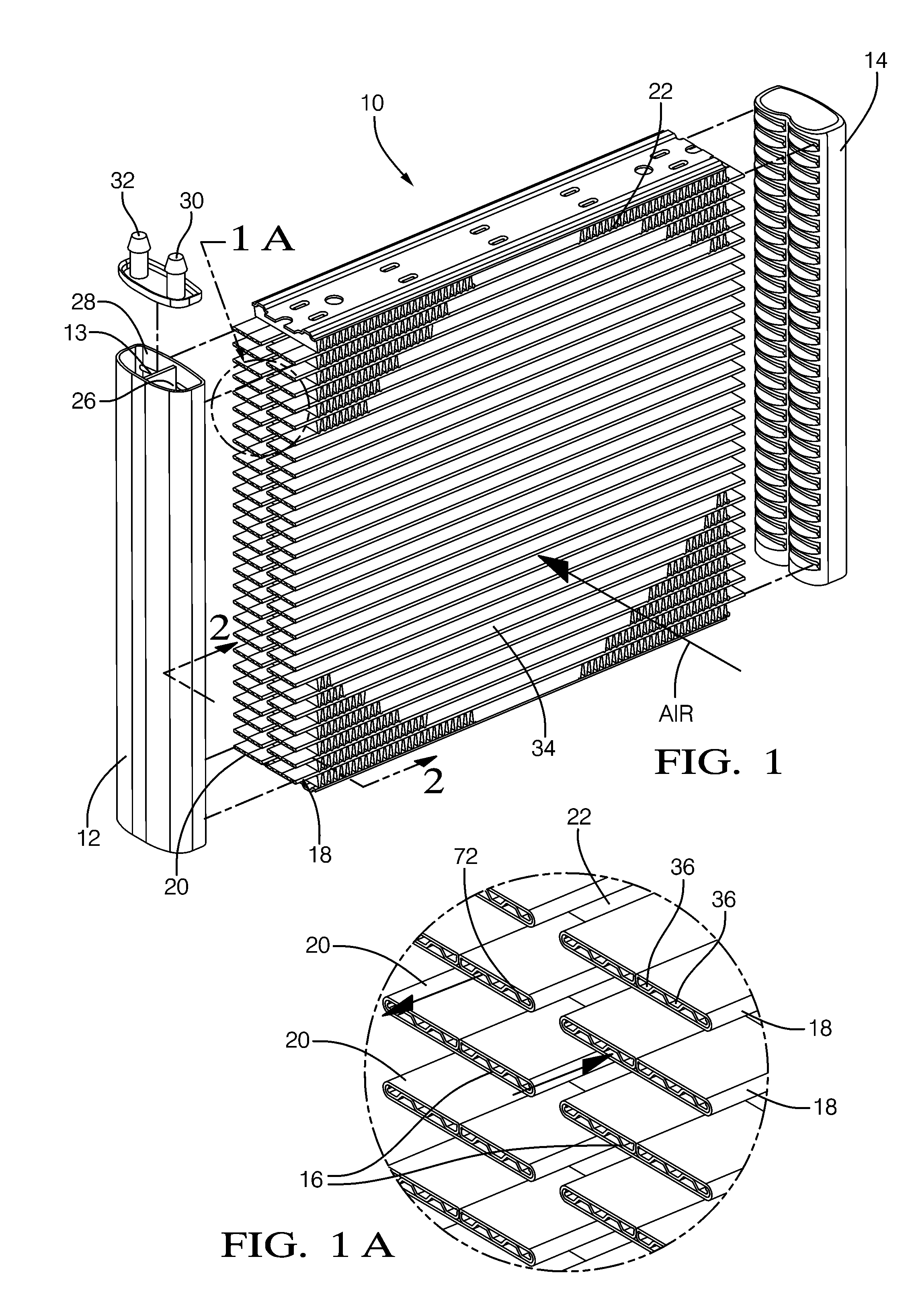
[0022]Referring to the FIGS. 1 through 3, wherein like numerals indicate corresponding parts throughout the views, is an embodiment of an evaporator 10 having evaporator tubes 16 with features that improve the operating characteristics of the evaporator 10. Shown in FIG. 1 is a perspective view of an evaporator 10 having dual banks 18, 20 of evaporator tubes 16 for use in a motor vehicle. The evaporator 10 is typically housed in a HVAC module of a motor vehicle and includes a plurality of evaporator tubes 16 hydraulically connecting two spaced apart headers 12, 14 for a two-phase refrigerant flow therebetween. For an exemplary two-pass evaporator 10, the first header 12 is typically an inlet / out let header defining a cavity that includes a substantially center partition 13 extending the length of the first header 12 and separates the cavity into an inlet chamber 26 and an outlet chamber 28. The inlet chamber 26 is in hydraulic communication with an inlet port 30 and the outlet chamb...


PUM


Abstract

An evaporator assembly having a first header, a second header, at least two banks of evaporator tubes extending therebetween and in hydraulic communication with the first and second headers. At least one of the evaporator tube may be folded from a unitary strip clad aluminum folded having a thickness (t). The evaporator tube includes a height (h) which is measured from the bottom exterior surface to the top exterior surface, and a corner radius (rc) defined by the transition radius from the flange segments to the channel walls. The bottom wall includes a width (2w), the corrugated portion includes alternating flange segments abutting the interior surface and channel walls connecting the alternating flange segments, at least one of the alternating adjacent flange segments includes a length (a) cooperating with adjacent the channel walls to define a channel having a width (b). The evaporator tube also includes a number of ports per millimeter width (PPMW) in a range of 0.40 to 1.0 as defined by the equation PPMW=2/(a+b+t); a Port Shape (PS) ratio of 0.05 to 0.6 as defined by the equation PS ratio=a/b; a non-dimensional gauge (NDG) ratio of 0.11 to 0.21 as defined by the equation NDG ratio=t/h; and a non-dimensional corner radius (NDCR) ratio of 0.10 to 0.5 as defined by the equation NDCR ratio=rc/2t.

Description

CROSS-REFERENCE TO RELATED APPLICATION[0001]This application claims the benefit of U.S. Provisional Patent Application Ser. No. 61 / 346,522 for a FABRICATED TUBE EVAPORATOR, filed on May 20, 2010, which is hereby incorporated by reference in its entirety.TECHNICAL FIELD OF INVENTION[0002]The present invention relates generally to a tube for a heat exchanger; specifically, to a fabricated tube for an evaporator; and more specifically, to a folded evaporator tube.BACKGROUND OF INVENTION[0003]A heat exchanger assembly such as a radiator, condenser, or evaporator for use in a motor vehicle typically includes an inlet header, an outlet header, a plurality of tubes hydraulically connecting the headers for fluid flow therebetween, and external fins interconnecting the tubes. The headers, tubes, and fins are typically assembled into a unitary structure and brazed to form the heat exchanger assembly.[0004]A first heat transfer fluid, such as a liquid coolant, flows from the inlet header to th...

Claims


Application Information

Patent Timeline
IPC IPC(8): F28F9/02F28F1/00
CPCF28D1/0391F28F1/022F28D1/05383
Inventor CHOWDHURY, SOURAVKADLE, PRASAD S.
Owner MAHLE INT GMBH
Why Eureka
Try Eureka