Imaging element and imaging apparatus using the same

Active Publication Date: 2011-11-24
RICOH KK
View PDF9 Cites 14 Cited by
  • Summary
  • Abstract
  • Description
  • Claims
  • Application Information

AI Technical Summary

Benefits of technology

[0009]The present invention is to provide an imaging element capable of achieving a normal color reproduction as well as high resolution

Problems solved by technology

Therefore, there is a problem in that sensitivity is degraded in principle.
Furthermore, resolution of brightness information is degraded compared to the case where the filter is not used, so that low resolution of an obtained image is visible to the human eyes.
However, in the above conventional technology, there are problems in that, for example, when combining the brightness information and the color information, if a sampling period of the color information is small in relation to

Method used


Image

  • Imaging element and imaging apparatus using the same
  • Imaging element and imaging apparatus using the same
  • Imaging element and imaging apparatus using the same

Examples


first embodiment

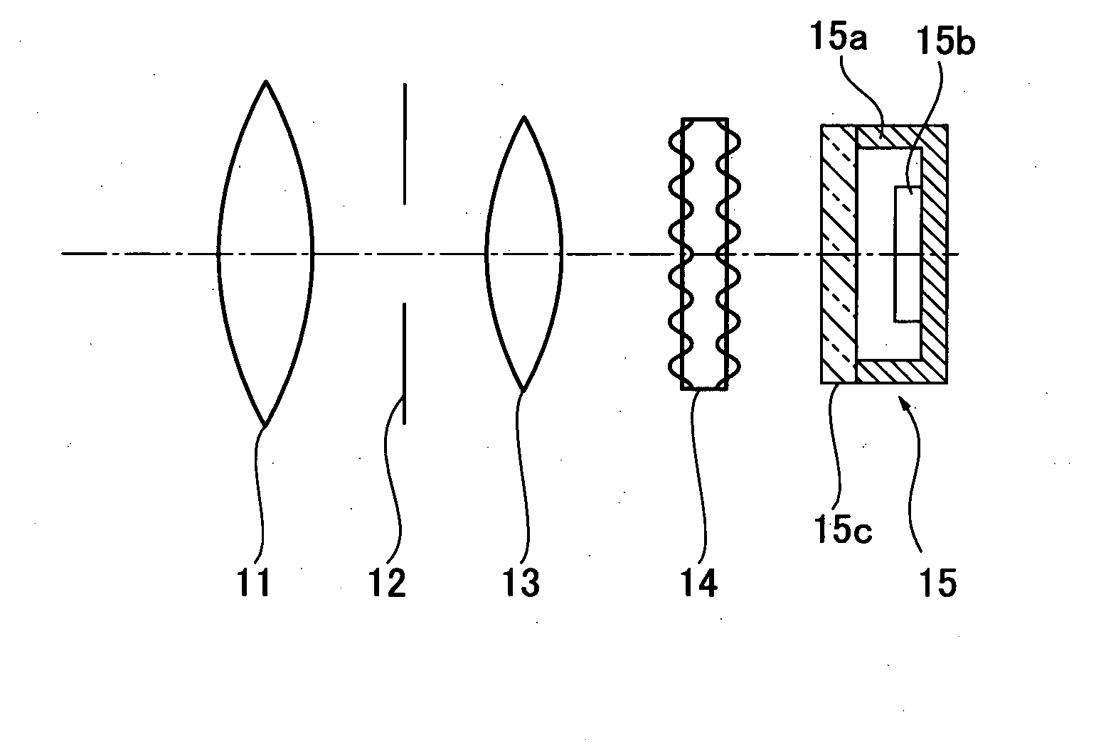
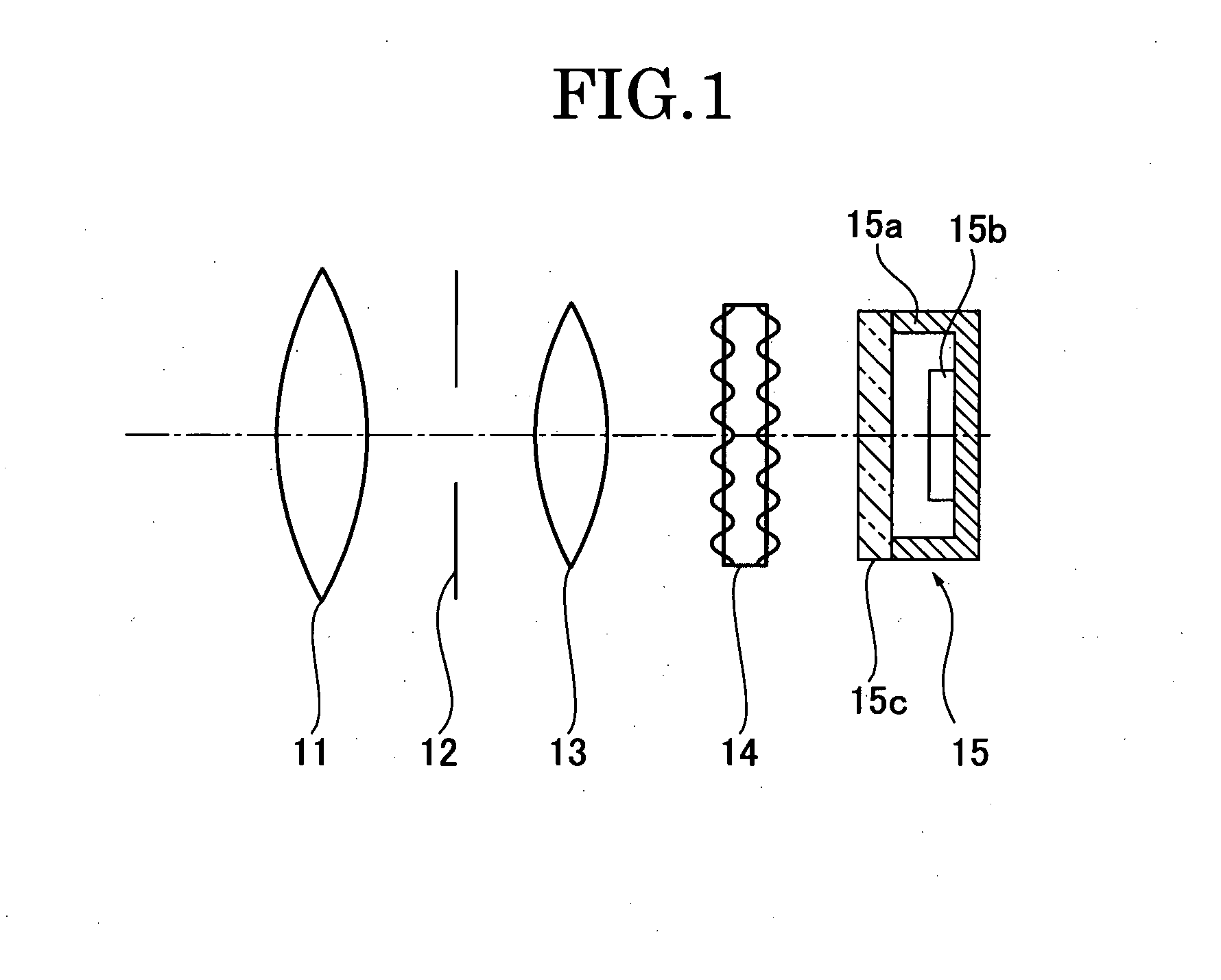
[0048]FIG. 1 is a configuration diagram illustrating an imaging optical system including an imaging element according to an embodiment of the present invention. A left side of FIG. 1 indicates a subject side and a right side of FIG. 1 indicates an imaging plane side. Reference number 11 indicates a lens system 11 formed by one or more lenses, reference number 12 indicates an aperture stop to set an F number within about 1 to 3, reference number 13 indicates a lens system formed by one or more lenses, and reference number 15 indicates an imaging element body. The lens system 11 is disposed at the subject side from the aperture stop 12 and the lens system 13 is disposed at the imaging plane side from the aperture stop 12. The lens system 11, the aperture stop 12 and the lens system 13 are disposed on an optical axis L.

[0049]On the optical axis L, the low-pass filter 14 and the imaging element body 15 are disposed in order from a side close to the lens system 13. In this embodiment, th...

second embodiment

[0102]The low-pass filter may have a polarization-dependent characteristic changing depending on a polarization direction of the predetermined light.

[0103]The polarization-dependent characteristic of the low-pass filter may be a characteristic to transmit only a predetermined polarization light component

[0104]Next, a second embodiment of the present invention will be explained. Although the wavelength-selective low-pass filter is used in the first embodiment, a polarization-selective low-pass filter is used in this embodiment.

[0105]In this embodiment, as the low-pass filter 14, a diffracting grating having light-polarization selectivity is formed. At first, with reference to FIG. 13, transmissive characteristics of light beams polarized in relation to a birefringent medium will be explained. FIG. 13 is a view illustrating paths of the light beams in a case where the light beams enter and transmit the general birefringent medium. When the light beams enter the birefringent medium, a ...


PUM


Abstract

An imaging element includes a light receiving surface having pixels, and a low-pass filter device configured to focus predetermined light on a predetermined pixel of the pixels of the light-receiving surface.

Description

[0001]This application is based on and claims priority from Japanese Patent Application No. 2009-014195, filed on Jan. 26, 2009, the disclosure of which is incorporated herein by reference in its entirety.TECHNICAL FIELD[0002]The present invention relates to an imaging element which is used in an imaging apparatus such as a digital camera, or the like and an imaging apparatus having the same.BACKGROUND ART[0003]Conventionally, for use of a back-monitor of a vehicle, an high sensitive imaging apparatus capable of obtaining a color image has been known. Recently, multifunctional imaging apparatus capable of, for example, imaging a polarized image for detecting a wet state of a road surface with a high sensitivity has been required.[0004]In a conventional technique, when a color image or a polarized image is obtained, methods for demosicing an obtained image by providing a color filter on each pixel of the imaging element (see, for example, Japanese Patent Application Publication No. 2...

Claims


Application Information

Patent Timeline
IPC IPC(8): H04N5/225G03B7/00G02B5/18G02B5/20G02B5/30H01L27/14H04N9/07H04N101/00
CPCG02B5/1885H01L27/14621H01L27/14629H04N5/238H04N9/045H04N5/2254H04N23/75H04N23/84H04N25/134H04N23/12
Inventor KASAHARA, RYOSUKEHIRAI, HIDEAKI
Owner RICOH KK
Why Eureka
Try Eureka