Projection optical system and projection type display using the same

a projection optical system and optical axis technology, applied in the direction of microscopes, telescopes, instruments, etc., can solve the problem of missing parts outside the effective area of the lens, and achieve the effect of reducing the distance between the image plane on the screen and reducing the size of the apparatus in the direction of the optical axis of the first optical system, and reducing the size of the apparatus in the direction of the optical axis of the firs

Inactive Publication Date: 2011-11-24
BABA TOMOYUKI
View PDF11 Cites 4 Cited by
  • Summary
  • Abstract
  • Description
  • Claims
  • Application Information

AI Technical Summary

Benefits of technology

[0021]According the first projection optical system and the projection type display using the same of the present invention, the overall length T1 of the first optical system with respect to the maximum light ray height Y on the image display device is set so as to be within a range smaller than 12.5. That is, since the size of the projection optical system is reduced, first, by reducing the overall length of the first optical system, by setting the overall length T1 of the first optical system so as to be smaller than 12.5 with respect to the maximum light ray height Y on the image display device, the apparatus size can be reduced to a sufficiently satisfactory degree also when the optical system is mounted in the front projection type.
[0022]The first optical system and the second optical system are disposed in order from the side of the reduction side conjugate plane of the pair of conjugate planes, the first optical system includes a plurality of lenses, the second optical system includes the reflecting mirror having an aspheric concave configuration, and the intermediate image is formed between the first optical system and the second optical system. Consequently, even though the angle of incidence is large in the oblique incidence optical system, a real image with little distortion can be formed on the screen by using a small number of reflecting mirrors, and the generation of chromatic aberration can be suppressed compared with when the projection optical system is constituted only by a dioptric system. Moreover, since the second optical system includes one reflecting mirror, the assembly of the optical system is easy, and the size reduction of the apparatus can be promoted.
[0024]According to the second projection optical system and the projection type display using the same of the present invention, the first optical system and the second optical system are disposed in order from the side of the reduction side conjugate plane of the pair of conjugate planes, the first optical system includes from the side of the image display device a first lens group having positive refractive power, a second lens group having negative refractive power, and a third lens group having low refractive power (having positive or negative refractive power), the second optical system includes the reflecting mirror having an aspheric concave configuration, and the intermediate image is formed between the first optical system and the second optical system. Consequently, even though the angle of incidence is large in the oblique incidence optical system, a real image with little distortion can be formed on the screen by using a small number of reflecting mirrors, and the generation of chromatic aberration can be suppressed compared with when the projection optical system is constituted only by a dioptric system. Moreover, since the second optical system includes one reflecting mirror, the assembly of the optical system is easy, and the size reduction of the apparatus can be promoted.
[0026]According to the third projection optical system and the projection type display of the present invention, since the distance between the image plane on the screen and the optical axis of the first optical system can be significantly reduced when the light ray traveling from the reflecting mirror toward the screen starts to interfere with the most magnification side lens of the first optical system, the apparatus size in the direction vertical to the optical axis of the first optical system can be reduced.
[0027]Since the first optical system can be disposed nearer to the reflecting mirror for the same purpose, the apparatus size in the direction of the optical axis of the first optical system can be reduced.
[0029]The first optical system and the second optical system are disposed in order from the side of the reduction side conjugate plane of the pair of conjugate planes, the first optical system includes a plurality of lenses, and the second optical system includes the reflecting mirror having an aspheric concave configuration. Consequently, even though the angle of incidence is large in the oblique incidence optical system, a real image with little distortion can be formed on the screen by using a small number of reflecting mirrors, and the generation of chromatic aberration can be suppressed compared with when the projection optical system is constituted only by a dioptric system. Moreover, since the second optical system includes one reflecting mirror, the assembly of the optical system is easy, and the size reduction of the apparatus can be promoted.

Problems solved by technology

And the missing part is outside the effective area of the lens and interferes with a light ray traveling from the second optical system toward the screen.

Method used


Image

  • Projection optical system and projection type display using the same
  • Projection optical system and projection type display using the same
  • Projection optical system and projection type display using the same

Examples


first example

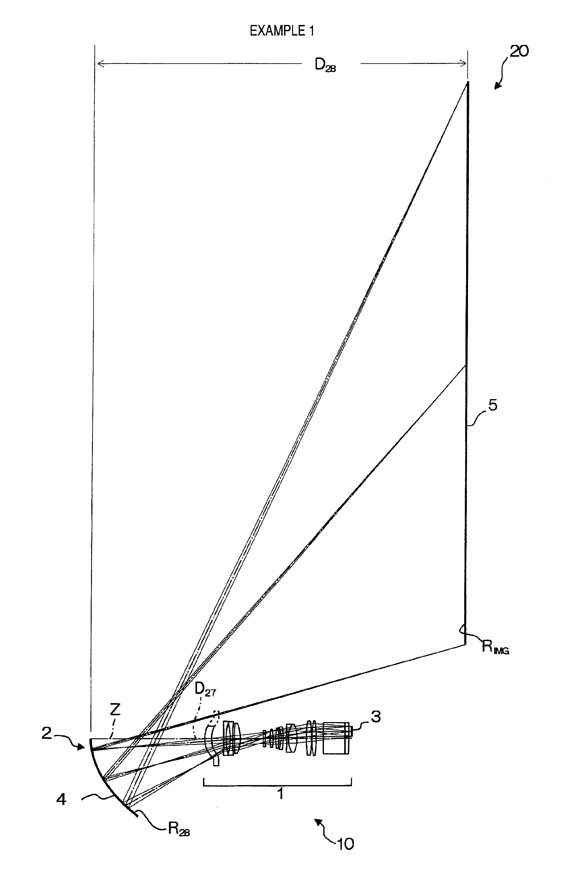
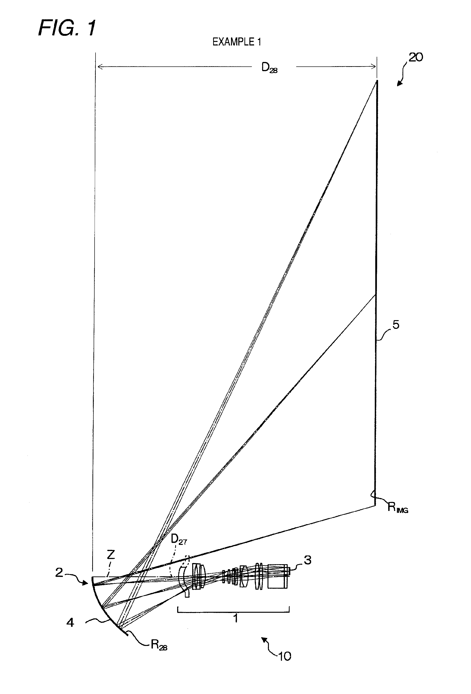
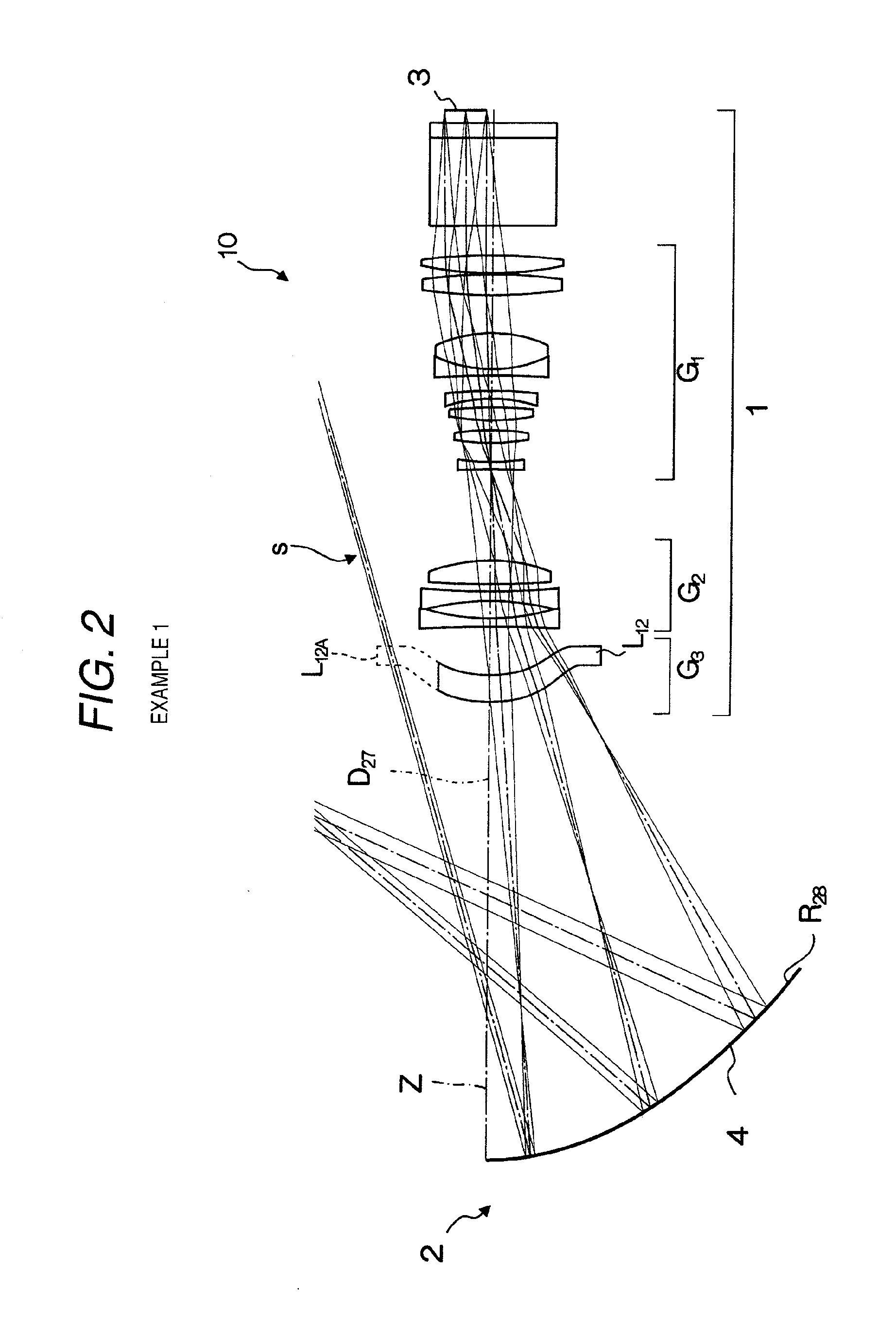
[0068]The structure of the projection type display 20 according to the first example is as shown in FIG. 1. The structure of the projection optical system 10 is as shown in FIG. 2. The detailed structure of the lens system constituting the first optical system 1 thereof is as shown in FIG. 3.

[0069]As shown in FIGS. 2 and 3, the first optical system 1 emits a luminous flux carrying image information which luminous flux is emitted from the image display device 3 disposed on the side above the optical axis Z in the figure, toward the reflecting mirror 4 included in the optical system 2 on the reduction side. The first optical system 1 is a so-called off-axial optical system, and includes in order from the object side: a cover glass (plane-parallel plate) 6, a prism section 7, a positive first lens group G1 including eight lenses L1 to L8; an aperture diaphragm 8; a second lens group G2 including three lenses L9 to L11; and a third lens group G3 (slightly negative near the optical axis)...

second embodiment

[0077]The structure of the projection type display 20 according to the second example is as shown in FIG. 5. The structure of the projection optical system 10 is as shown in FIG. 6. The detailed structure of the lens system constituting the first optical system 1 thereof is as shown in FIG. 7.

[0078]While the projection type display 20 and the projection optical system 10 according to the present example are structured substantially similarly to the projection type display 20 and the projection optical system 10 according to the first example as shown in FIGS. 6 and 7, they are different, particularly, in that the first lens group G1 includes seven lenses L1 to L7. The second lens group G2 includes three lenses L8 to L10, and the third lens group G3 includes one aspheric lens L11 that is slightly positive near the optical axis.

[0079]A rotationally asymmetric shape is adopted where the part L11A is missing that is outside the effective area of the lens L11 and interferes with the ligh...


PUM


Abstract

A luminous flux optically modulated by an image display device is projected to be magnified on a screen by a projection optical system includes: a first optical system having a positive first lens group including eight lenses, a negative second lens group including three lenses, and a third lens group including an aspheric single lens; and a second optical system including an aspheric reflecting mirror. The projection optical system is an off-axial optical system, and forms the intermediate image between the first optical system and the second optical system. Moreover, the expressions T1 / Y<12.5 and T12 / f1<6.0 are satisfied where T1 is the overall length of the first optical system, Y is the maximum light ray height on an image display device, T12 is the distance between the first optical system and the second optical system, and f1 is the focal length of the first optical system.

Description

CROSS-REFERENCE TO RELATED APPLICATIONS[0001]This application is a Divisional of co-pending application Ser. No. 12 / 420,600, filed on Apr. 8, 2009, and for which priority is claimed under 35 U.S.C. §120. This application claims priority under 35 USC 119 from Japanese Patent Application No. 2008-101705 filed Apr. 9, 2008, and Japanese Patent Application No. 2008-101706 filed Apr. 9, 2008; the entire contents of which are incorporated herein by reference.BACKGROUND[0002]1. Technical Field[0003]The present invention relates to a projection optical system and a projection type display, and more particularly, to a projection optical system that forms an image displayed on an image display device, on a screen by using a first optical system including a plurality of lenses and a second optical system including a concave mirror, and a projection type display using the same.[0004]2. Related Art[0005]As projection optical systems for projection type displays and projection type televisions, o...

Claims


Application Information

Patent Timeline
Patent Type & Authority Applications(United States)
IPC IPC(8): G02B17/08
CPCG02B17/08G02B13/16
Inventor BABA, TOMOYUKI
Owner BABA TOMOYUKI
Why Eureka
Try Eureka