Receiver having clock recovery unit based on delay locked loop

a clock recovery and clock technology, applied in the direction of synchronous/start-stop systems, digital transmission, instruments, etc., can solve the problems of oscillation frequency and phase being likely to be distorted, jitter continuously accumulating, and jitter continuously accumulating

Active Publication Date: 2011-11-24
SILICON WORKS CO LTD
View PDF3 Cites 40 Cited by
  • Summary
  • Abstract
  • Description
  • Claims
  • Application Information

AI Technical Summary

Benefits of technology

[0018]Accordingly, the present invention has been made in an effort to solve the problems occurring in the related art, and an object of the present invention is to provide a receiver having a clock recovery unit based on a delay locked loop, wherein a PLL (phase locked loop) structure in which an input signal (a clock-embedded data (CED) signal) received through a signal line is not inputted to a VCO (voltage-controlled oscillator) and is compared, in terms of phase, with a reference clock signal as an internal clock signal generated by a separate internal oscillator and the phase of the internal clock signal is adjusted to be used for the recovery of data, is excluded, and only a delay locked loop is employed to recover a clock signal in such a manner that an input signal (a clock-embedded data (CED) signal) is directly inputted to a delay line (VCDL) and is delayed and a reference clock signal is generated without using a separate internal oscillator to be used for the recovery of data, thereby preventing jitter from accumulating in a receiver which does not separately use a clock signal, due to continuous transmission of the clock signal through a feedback loop.

Problems solved by technology

However, the conventional clock generation unit configured based on the phase locked loop (PLL) structure has a problem in that jitter continuously accumulates in the phase lock loop (PLL) as an internal feedback loop.
Nevertheless, the conventional clock generation unit, which is configured to operate by the delay locked loop (DLL) structure in the initial synchronization and by the phase lock loop (PLL) structure after the initial synchronization, has a problem in that the oscillation frequency and the phase are likely to be distorted due to the change of the loop during operation.
Further, since the enable signal is generated by the phase locked loop (PLL) structure after the initial synchronization, a problem is still caused in that jitter continuously accumulates in the phase locked loop (PLL) as an internal feedback loop.

Method used


Image

  • Receiver having clock recovery unit based on delay locked loop
  • Receiver having clock recovery unit based on delay locked loop
  • Receiver having clock recovery unit based on delay locked loop

Examples


Embodiment Construction

[0027]Reference will now be made in greater detail to a preferred embodiment of the invention, an example of which is illustrated in the accompanying drawings. Wherever possible, the same reference numerals will be used throughout the drawings and the description to refer to the same or like parts.

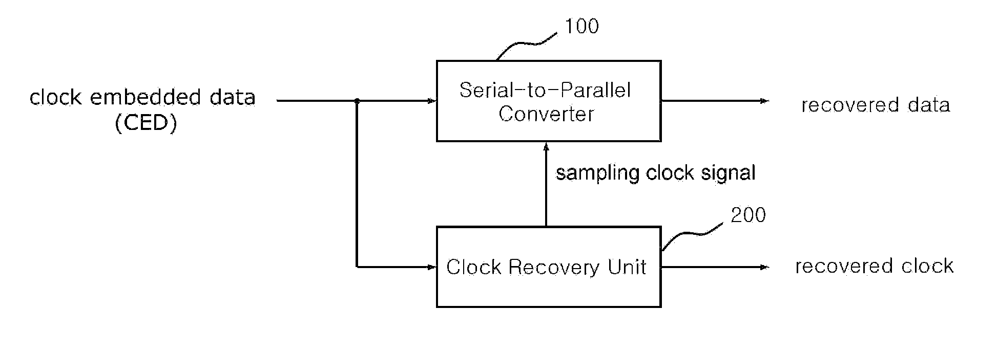
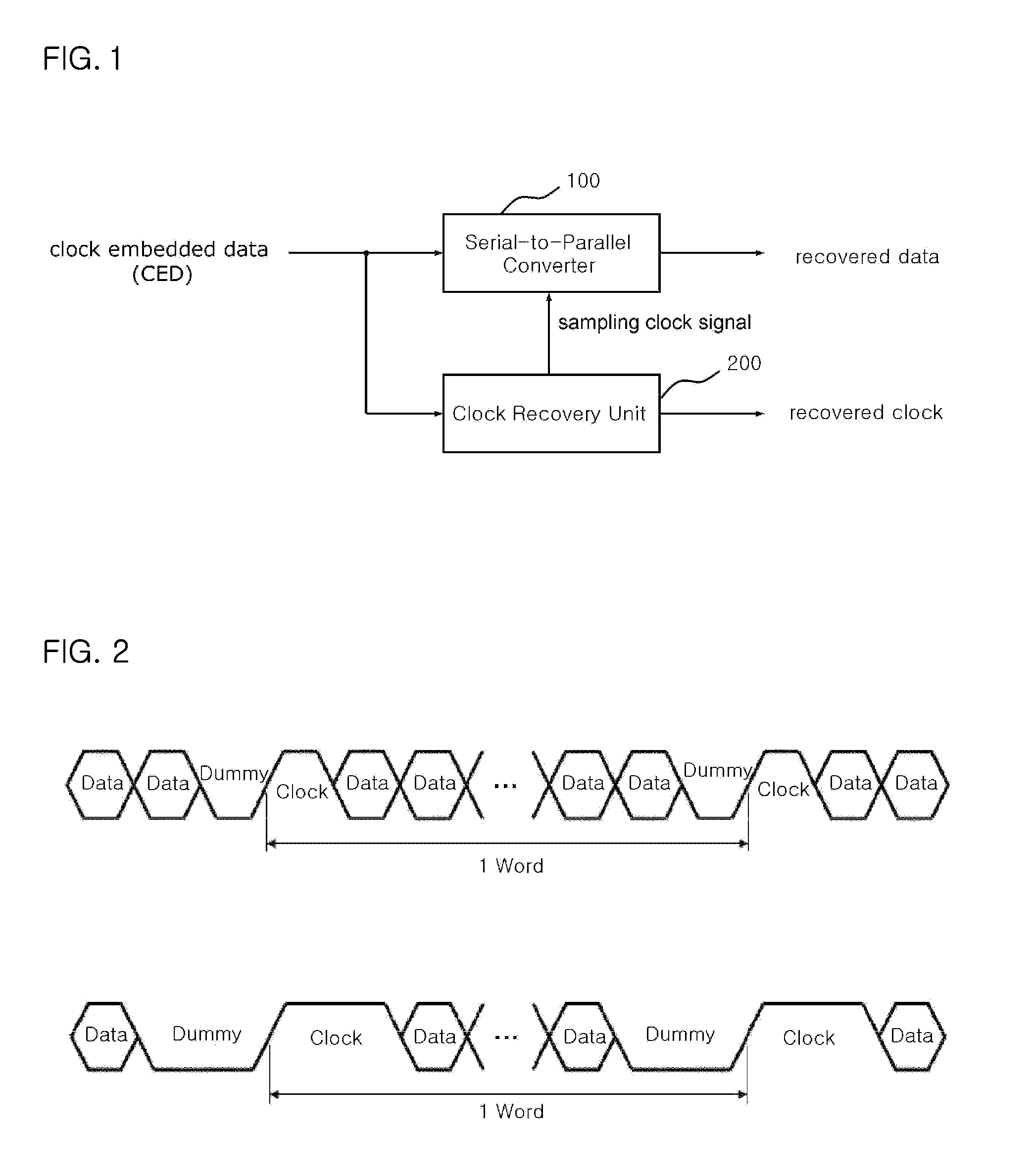
[0028]FIG. 1 is a block diagram illustrating a receiver for receiving a single level signal with an embedded clock signal in accordance with an embodiment of the present invention.

[0029]Referring to FIG. 1, a receiver for receiving a single level signal embedded with a clock signal includes a serial-to-parallel converter 100 configured to receive a single level signal (clock embedded data: CED) transmitted through a serial signal line from a timing controller, convert the single level signal into parallel data and transmit recovered data to a display panel, and a clock recovery unit 200 configured to extract a clock signal embedded in the single level signal (CED signal), transmit to the s...


PUM


Abstract

A receiver for receiving an input signal (a clock-embedded data (CED) signal), in which a clock signal is periodically embedded between data signals, includes a clock recovery unit configured to recover and output the clock signal and a serial-to-parallel converter configured to recover and output a data signal. The input signal (the CED signal) comprises a single level signal in which the clock signal is periodically embedded between the data signals at the same level. The clock recovery unit is configured based on a delay locked loop (DLL) without using an internal oscillator for generating a reference clock signal.

Description

BACKGROUND OF THE INVENTION[0001]1. Field of the Invention[0002]The present invention relates to a receiver of a display driving system, and more particularly, to a receiver having a clock recovery unit based on a delay locked loop, wherein a PLL (phase locked loop) structure is excluded and a clock recovery unit realized using only a DLL (delay locked loop) structure without using a separate oscillator for generating a reference clock signal is employed so that a clock signal embedded between data signals to the same level can be recovered.[0003]2. Description of the Related Art[0004]In general, display devices include a timing controller which processes image data and generates a timing control signal so as to drive a panel for displaying the image data, and data drivers which drive the panel using the image data and the timing control signal transmitted from the timing controller.[0005]Interfaces for transmitting image data to be displayed, between the timing controller and the d...

Claims


Application Information

Patent Timeline
Patent Type & Authority Applications(United States)
IPC IPC(8): H04L7/00
CPCG09G3/20G09G5/008G09G2310/027H03L7/0812G09G2370/08H03L7/0807G09G2310/08H03L7/0816H03L7/08
Inventor JEON, HYUN-KYUMOON, YONG-HWAN
Owner SILICON WORKS CO LTD
Why Eureka
Try Eureka