System for wireless communications through sea vessel hull

a wireless communication and sea vessel technology, applied in the direction of near-field transmission, transmission, electric devices, etc., can solve the problems of limiting the available bandwidth, unable to control the signal path, and affecting the operation of the vessel, so as to achieve high data rate, high bandwidth communication, and high data rate

Inactive Publication Date: 2011-11-24
WIRELESS FIBER SYST
View PDF23 Cites 12 Cited by
  • Summary
  • Abstract
  • Description
  • Claims
  • Application Information

AI Technical Summary

Benefits of technology

[0011]Advantageously, the system of the present invention is capable of providing high data rate and high bandwidth communications and/or data transfer through the sea vessel hull.
[0012]The present invention provides a system for wireless communications and/or data transfer through a sea-vessel hull by means of electric and/or magnetic coupling between first and second transducers located on opposing sides of the hull. Transmit and receive transducers are clamped around cables and/or other protrusions which penetrate the hull and which are fed through pressure hull glands in the hull. The inductive transducers couple electric and/or magnetic signals through the sea vessel hull via paths through the press

Problems solved by technology

However, acoustic signaling has the drawback that the signal path cannot be controlled.
Acoustic signaling thus suffers from the effects of multi-path interference which limits the available bandwidth for signals
Nonetheless,

Method used


Image

  • System for wireless communications through  sea vessel hull
  • System for wireless communications through  sea vessel hull
  • System for wireless communications through  sea vessel hull

Examples


first embodiment

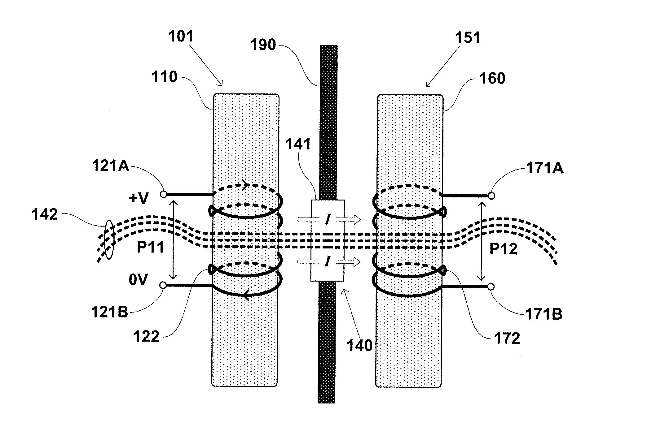
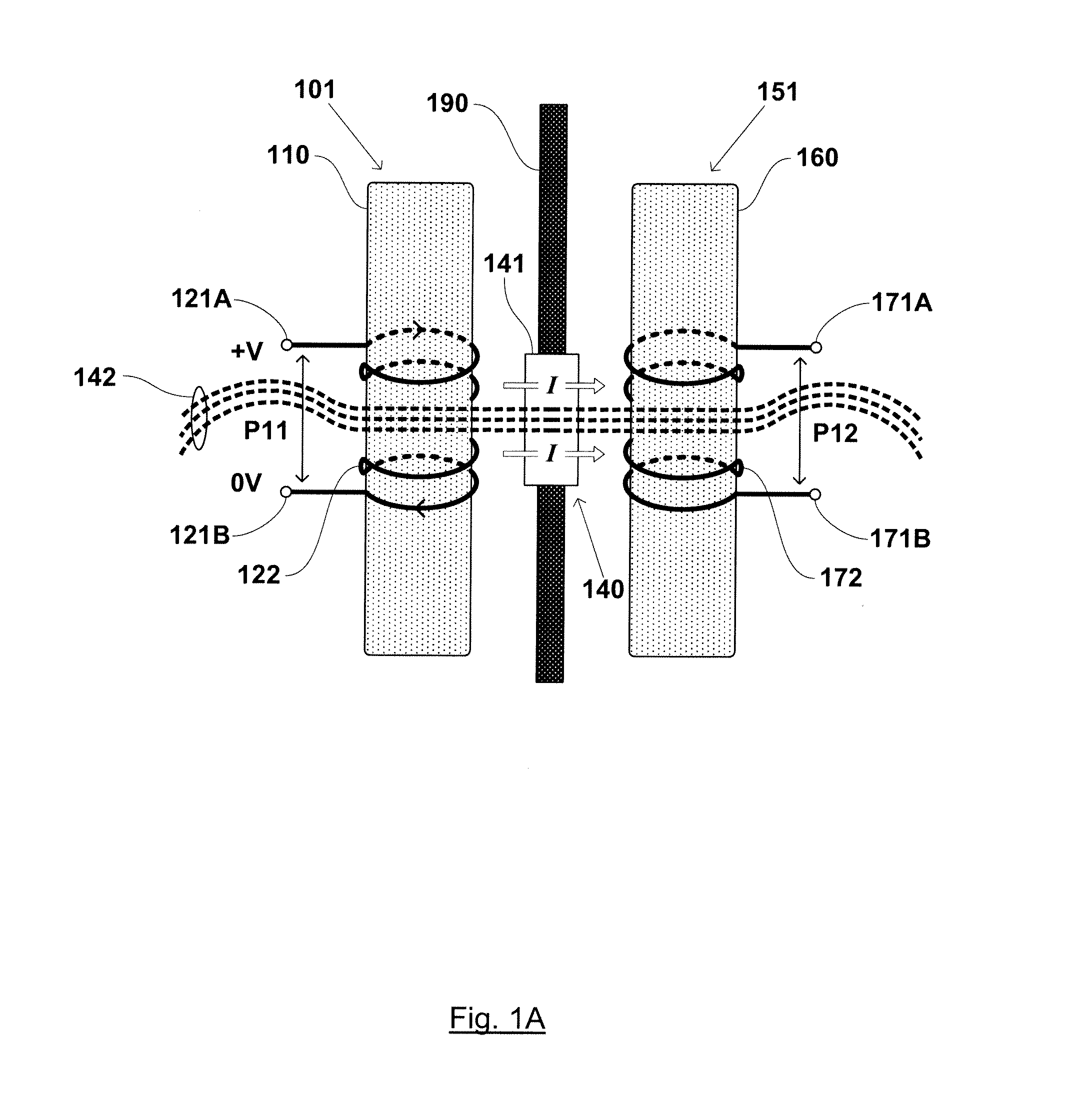
[0043]FIG. 1A shows a side view drawing of a system for wireless communications through a sea vessel hull 190 according to the present invention. The generic term communications here and elsewhere implicitly refers to any or all of: transmission and / or reception of communications signals, transmission and / or reception of control signals and transmission and / or reception of data.

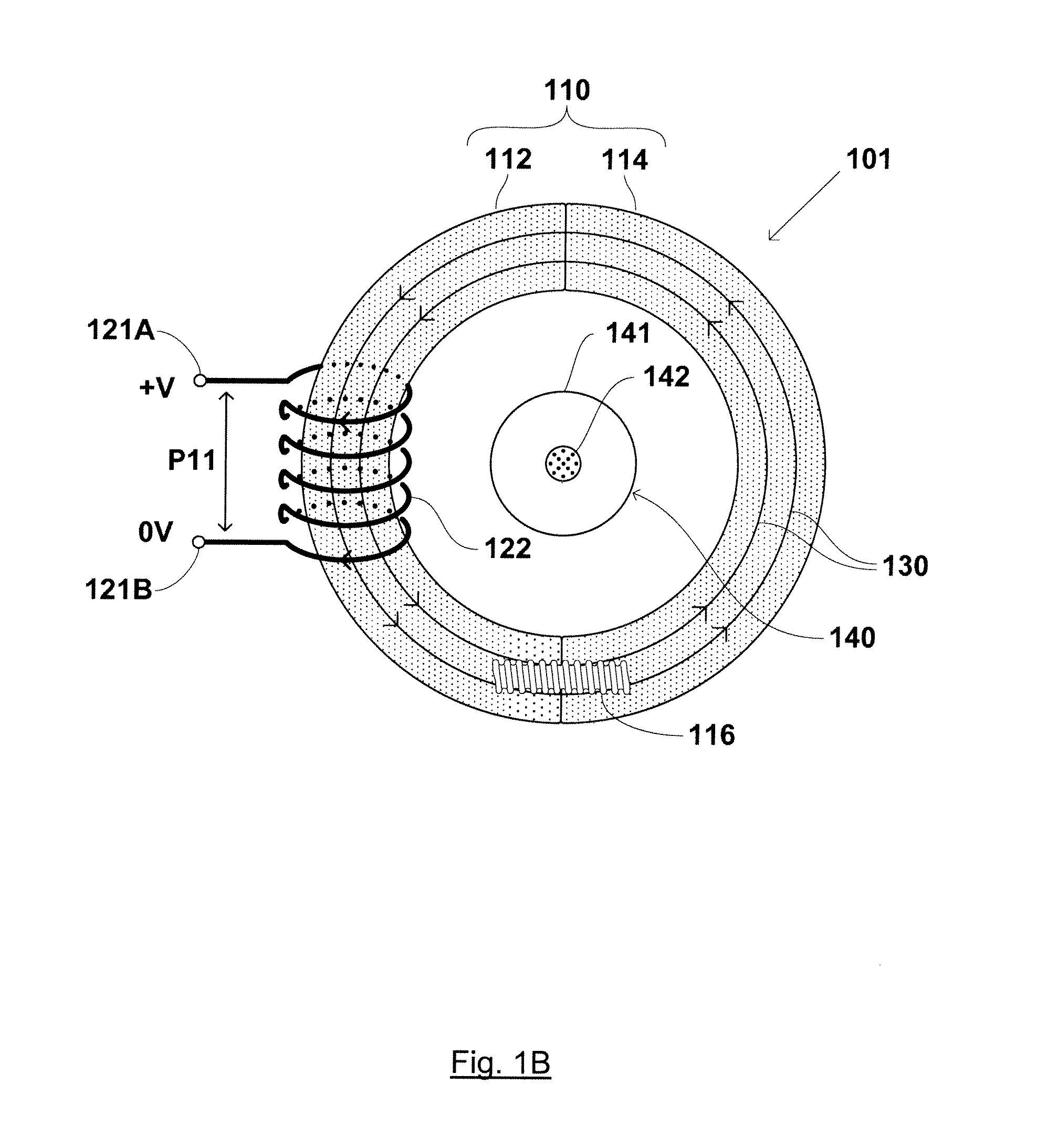
[0044]The system of FIG. 1A comprises a first transducer 101 comprising a first transducer coil 122 formed over a magnetic permeable toroidal core 110. First transducer coil 122 is wound of electrically conductive wire having an electrically insulating outer coating. First transducer coil 122 comprises input terminals 121A, 121B across which a voltage differential V may be applied. First transducer 101 is located so that the plane of toroidal core 110 is parallel to the plane of sea vessel hull 190. During use, one side of toroidal core 101 is positioned so that it is close to or flush against sea vessel hull...

second embodiment

[0057]FIG. 2A shows a side view drawing of a system for wireless communications through a sea vessel hull the present invention.

[0058]The system of FIG. 2A comprises a first transducer 201. First transducer 201 comprises a first transducer coil 222 formed of electrically conductive wire and having an electrically insulating outer coating. Coil 222 is wound over a portion of magnetic permeable annular core 210.

[0059]Annular core 210 has a first side S1 and a second side S2, both sides S1, S2 being perpendicular to a central axis of annular core 210. First side S1 faces away from sea vessel hull 290, and second side S2 faces towards sea vessel hull 290. Annular core 210 comprises three sections: an inner annular portion 215, an outer annular portion 217 and a flange portion 216. Flange portion 216 bridges between inner annular portion 215 and outer annular portion 217 at the first side S1 of annular core 210.

[0060]Annular core 260, similarly, has a first side and a second side (not s...

third embodiment

[0067]FIG. 3 shows a front view drawing of first transducer 301 for use in a system for wireless communications through a sea vessel hull according to the present invention.

[0068]Annular core 310 of FIG. 3 comprises three portions: an inner annular portion 315, an outer annular portion 317 and a flange portion (not shown) which bridges between inner annular portion 315 and outer annular portion 317.

[0069]Annular core 310 further can be divided into a pair of substantially equal sub-sections: first section 312 and second section 314. First section 312 and second section 314 may be secured together by a fixing bolt (not shown).

[0070]Transducer coil 322 is wound around inner annular portion 315 of annular core 310. Transducer coil 322 is formed of electrically conductive wire having an electrically insulating outer coating. Transducer coil 322 comprises input terminals 321A, 321B across which a voltage differential V may be applied.

[0071]Transducer coil 322 further comprises a first pl...


PUM


Abstract

The present invention discloses a system for wireless communications and/or data transfer through a sea-vessel hull by means of electric and/or magnetic coupling between first and second transducers located on opposing sides of the hull. Transmit and receive transducers located on opposing sides of the hull are clamped around cables which penetrate the hull and which are fed through pressure hull glands in the hull. The inductive transducers couple electric and/or magnetic signals through the sea vessel hull via paths through the pressure hull glands or via paths through the cables. The system for wireless communication and/or data transfer of the present invention is capable of operation through an electrically conductive sea vessel hull which would ordinarily present a physical barrier against the transmission of such signals. The system can be deployed on an ad ad-hoc basis and is capable of providing high data rate and high bandwidth communications and/or data transfer through the sea vessel hull. The system does not interfere with existing cabled systems penetrating the hull via the pressure hull glands. In particular, the system of the present invention requires no modification of existing hardware nor does it require any modification of the hull for operation.

Description

FIELD USE[0001]The present invention relates to the field of communications through the hull of a sea vessel.DESCRIPTION OF THE RELATED ART[0002]Wireless communications, data transfer and / or the transmission of control signals through the hull of a sea vessel are desirable for a range of applications. For example, on submarines, various external equipment, such as sonar, mast raising gear etc is located under the upper casing. This equipment, requires a communication means with associated internally located equipment which sends and receives data or control signals to the external equipment. Typically, the communications means between the internal and external equipment is via wired connections. Applications of wireless communications through a sea vessel hull also include systems for voice telephony or video streaming between a diver located on the outside of the vessel, and the crew located on the inside of the sea vessel. Wireless communications between the inside and the outside...

Claims


Application Information

Patent Timeline
IPC IPC(8): H04B5/00
CPCH04B5/0093H04B5/0031
Inventor CONWAY, GARETHDOBBIN, VINCENT WILLIAMKEARNS, BRIANHYLAND, BRENDAN
Owner WIRELESS FIBER SYST
Why Eureka
Try Eureka