
Microfluidic solution for high-throughput, droplet-based single molecule analysis with low reagent consumption

Active Publication Date: 2011-11-24
THE JOHN HOPKINS UNIV SCHOOL OF MEDICINE
View PDF2 Cites 31 Cited by
  • Summary
  • Abstract
  • Description
  • Claims
  • Application Information

AI Technical Summary

Benefits of technology

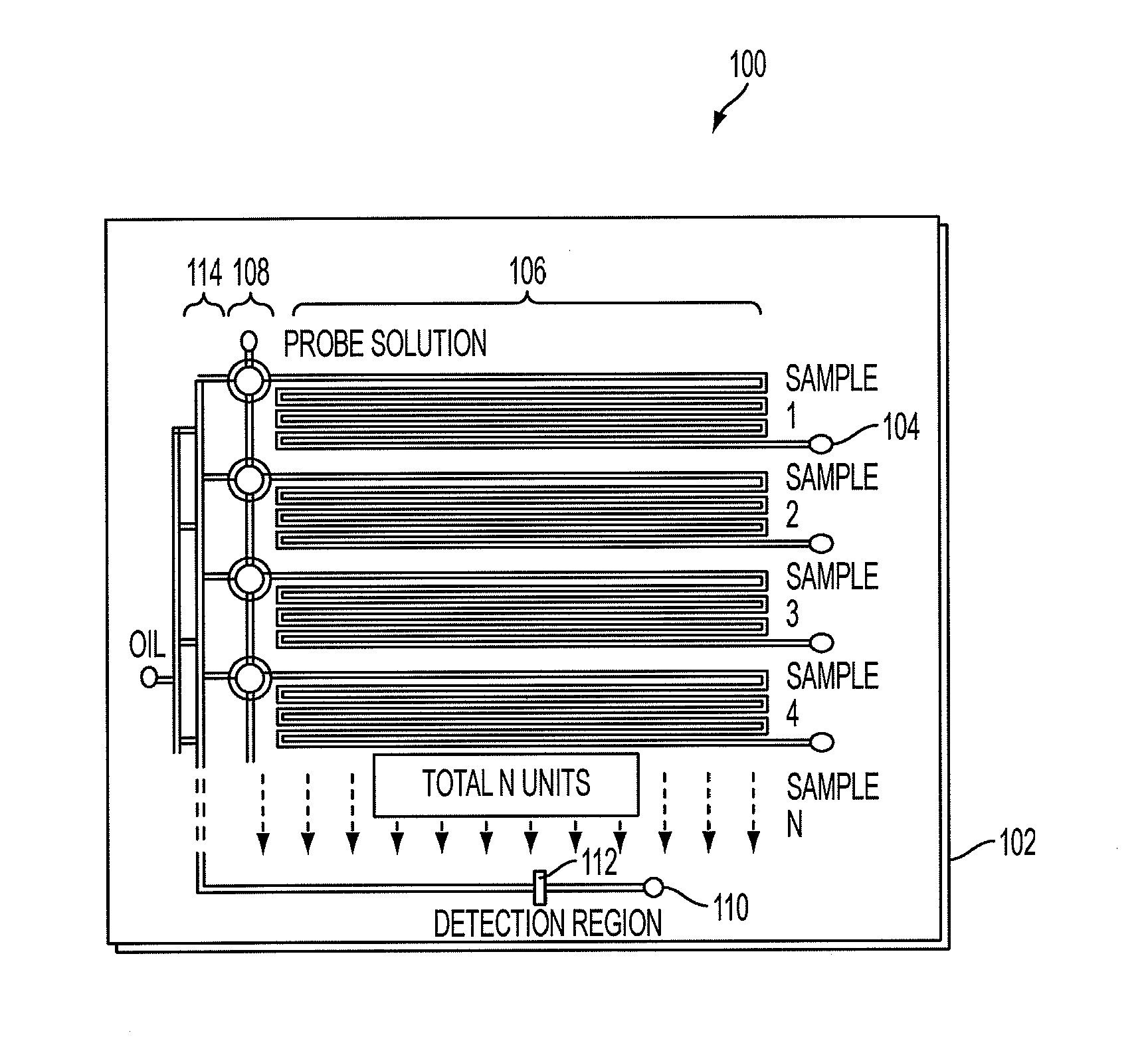
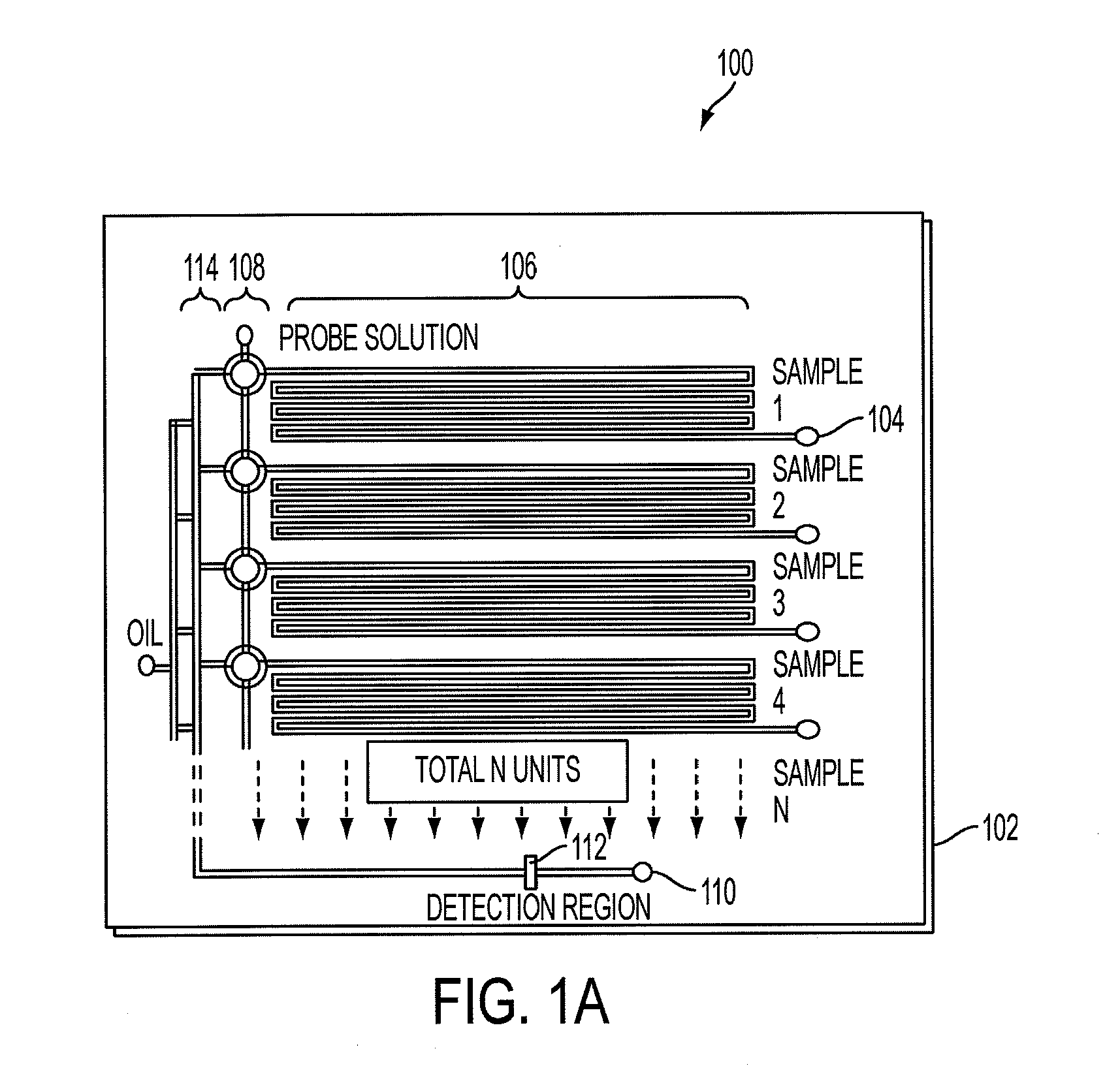
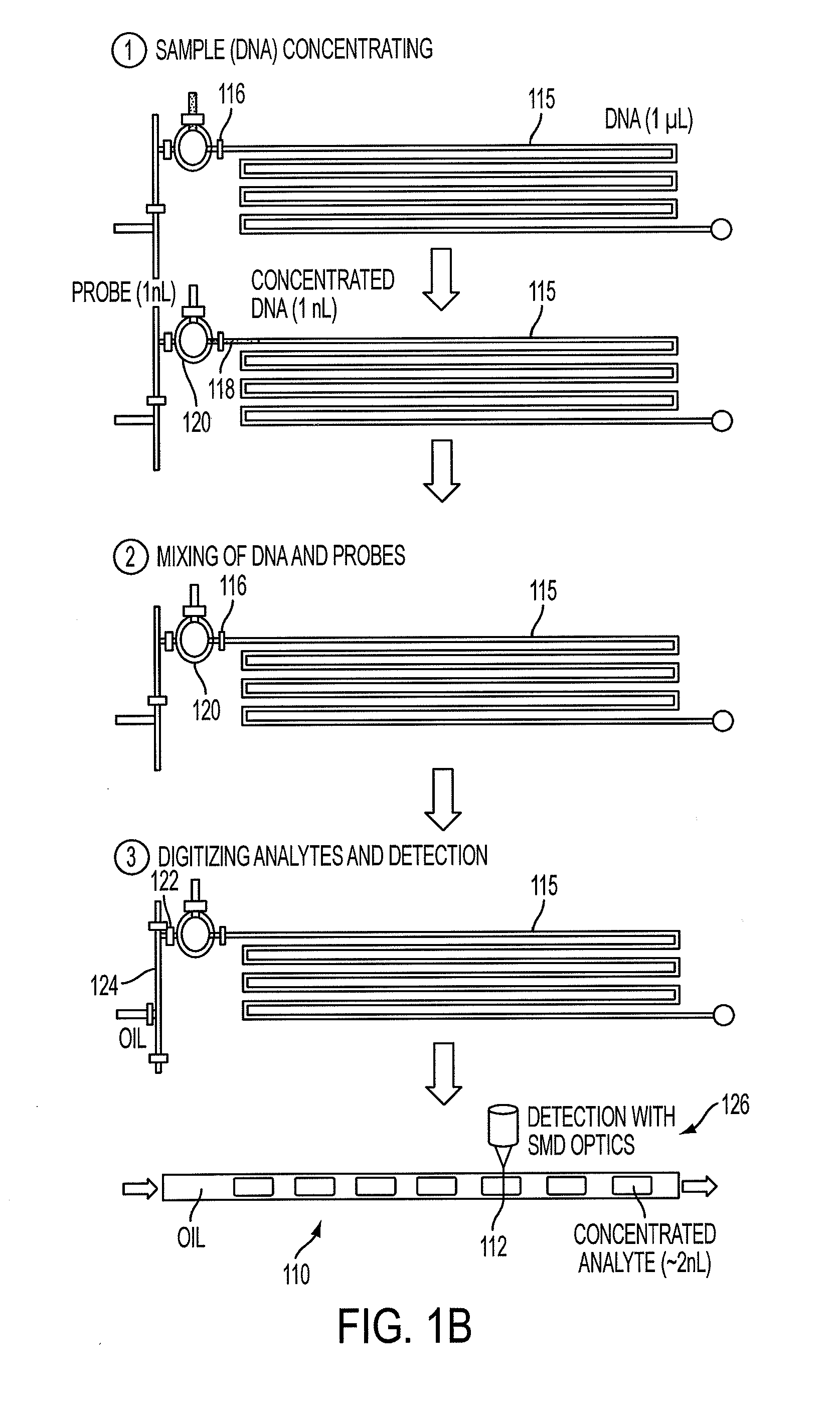
[0012]A method of detecting particles according to an embodiment of the current invention includes providing a sample comprising particles to be detected and a fluid in which the particles are at least one of suspended or dissolved, concentrating the sample by removing at least a portion of the fluid using a microfluidic device to provide a concent

Problems solved by technology

However, these same techniques have not translated well into the genomic era, where variations of molecular amplification techniques, such as polymerase chain reaction (PCR), remain the basis for detecting the accumulation of genetic alterations in cells and tissues.
Currently, many single molecule applications run for hours due to the inefficient probe-target interactions that occur when using extremely dilute and unamplified biological samples (L. A. Neely, S. Patel, J. Garver, M. Gallo, M. Hackett, S. McLaughlin, M. Nadel, J. Harris, S. Gullans and J. Rooke, Nat.
Although in principle SMD can be highly quantitative, its current implementations limit its accuracy, throughput, and practical applicability.
However, the diffraction-limited observation volume that enables SMD also significantly hampers its application in quantification and burst parameter determination.
In addition, since the observation volume profile is Gaussian in shape and highly non-uniform, a molecule's specific trajectory through the detection region will have a large influence on the emitted and collected fluorescence bursts, adding significant variability and uncertainty to not only the burst parameters but also their rate of detection.
However, these approaches have limitations in their practical application due to effectiveness, throughput limitations, reagent consumption and ease of use, for example.

Method used


Image

  • Microfluidic solution for high-throughput, droplet-based single molecule analysis with low reagent consumption
  • Microfluidic solution for high-throughput, droplet-based single molecule analysis with low reagent consumption
  • Microfluidic solution for high-throughput, droplet-based single molecule analysis with low reagent consumption

Examples


examples

[0063]In this example, we used inline, micro-evaporators according to an embodiment of the current invention to concentrate and transport DNA targets to a nanoliter single molecule fluorescence detection chamber for subsequent molecular beacon probe hybridization and analysis. This use of solvent removal as a unique means of target transport in a microanalytical platform led to a greater than 5,000-fold concentration enhancement and detection limits that pushed below the femtomolar barrier commonly reported using confocal fluorescence detection. This simple microliter-to-nanoliter interconnect for single molecule counting analysis resolved several common limitations, including the need for excessive fluorescent probe concentrations at low target levels and inefficiencies in direct handling of highly dilute biological samples. In this example, the hundreds of bacteria-specific DNA molecules contained in ˜25 microliters of a 50 aM sample were shuttled to a four nanoliter detection cha...


PUM

PropertyMeasurementUnit
Fractionaaaaaaaaaa
Fractionaaaaaaaaaa
Volumeaaaaaaaaaa

Abstract

A microfluidic device for a confocal fluorescence detection system has an input channel defined by a body of the microfluidic device, a sample concentration section defined by the body of the microfluidic device and in fluid connection with the input channel, a mixing section defined by the body of the microfluidic device and in fluid connection with the concentration section, and a detection region that is at least partially transparent to illumination light of the confocal fluorescence detection system and at least partially transparent to fluorescent light when emitted from a sample under observation as the sample flows through the detection region.

Description

CROSS-REFERENCE TO RELATED APPLICATIONS[0001]This application claims priority to U.S. Provisional Application No. 61 / 156,637 filed Mar. 2, 2009, the entire content of which is hereby incorporated by reference.[0002]This invention was made using U.S. Government support under NSF Grant No. BES-0546012 and NIH Grant No. CA120742. The U.S. Government has certain rights in this invention.BACKGROUND[0003]1. Field of Invention[0004]The current invention relates to microfluidic systems, and more particularly to microfluidic systems for high-throughput, droplet-based single molecule analysis with low reagent consumption.[0005]2. Discussion of Related Art[0006]Single molecule optical techniques have existed for decades and have provided researchers with techniques that enable dynamic measurements on the single-molecule scale that are not accessible in bulk. However, these same techniques have not translated well into the genomic era, where variations of molecular amplification techniques, suc...

Claims


Application Information

Patent Timeline
IPC IPC(8): C40B30/10C40B60/12
CPCB01L3/502769G01N15/1484B01L2400/0655G01N2001/4027G01N2021/6419B01L2200/10B01L3/502753G01N2015/0038B01L2300/088B01L7/52Y10T436/143333C12Q1/6825B01L2200/0678G01N2015/1493G01N21/6458G01N1/38G01N2021/6421B01L2400/0481
Inventor WANG, JEFF TZA-HUEILIU, KELVIN J.PULEO, CHRISTOPHER M.RANE, TUSHAR D.
Owner THE JOHN HOPKINS UNIV SCHOOL OF MEDICINE
Learn More