Hydraulic system for aircraft actuators

a technology for aircraft actuators and hydraulic systems, which is applied in the direction of machines/engines, servomotor parallel arrangements, and positive displacement liquid engines, etc. it can solve the problems of significant constraint on the continuous running time and the time for oil replacement associated with oil degradation, increase the overall temperature, and reduce the amount of heat generation in the hydraulic system. , to suppress the effect of an increase in the overall temperature of the hydraulic system, the effect of minimizing the amount of energy loss

Active Publication Date: 2011-12-01
NABLESCO CORP
View PDF9 Cites 25 Cited by
  • Summary
  • Abstract
  • Description
  • Claims
  • Application Information

AI Technical Summary

Benefits of technology

[0011]However, with the hydraulic system having this configuration, the electric power from the variable frequency supply is rectified by the power source unit, and moreover, the driver drives the electric motor so as to rotate the backup hydraulic pump at a predetermined constant rotational speed. Also, the predetermined constant rotational speed is set, based on the change in the efficiency of each of the backup hydraulic pump, the electric motor, and the driver with respect to the rotational speed (number of revolution) of the backup hydraulic pump, such that the overall efficiency, obtained as a product of multiplying these efficiencies, has a maximum value. This makes it possible to maintain the most efficient operational status of the hydraulic system as a whole, including the backup hydraulic pump, the electric motor, and the driver, thus minimizing the energy loss caused by heat generation in the hydraulic system. Accordingly, it is possible to minimize the amount of heat generation in the hydraulic system, thus suppressing an increase in the overall temperature of the hydraulic system. As a result, it is also possible to suppress an increase in the temperature of the oil used in the hydraulic system. Therefore, with this configuration, it is possible to provide a hydraulic system for aircraft actuators that can drive the actuator even in the case of a loss or reduction in the function of the aircraft central hydraulic power source, and can suppress an increase in the overall temperature of the system and the temperature of the oil used. In addition, in a hydraulic system having this configuration, the backup hydraulic pump is configured as a variable capacity hydraulic pump, and therefore the pressure of the pressure oil supplied to the actuator can be controlled by changing the capacity of the backup hydraulic pump, even when the backup hydraulic pump is rotated a predetermined constant rotational speed.

Problems solved by technology

This tends to cause an increase in the overall temperature of the hydraulic system including the pump, the electric motor, and the driver that supplies electric power to the electric motor, and also tends to cause an increase in the temperature of the oil (working fluid) that is supplied as the pressure oil from the pump to the actuator and that is circulated between the pump and the actuator.
Accordingly, there is a significant constraint on the continuous running time and the time for oil replacement associated with oil degradation.
That is, in a conventional hydraulic system, the heat generated in the electric motor and the backup hydraulic pump varies depending on the operating conditions, and therefore it is difficult to maintain an efficient operational status of the hydraulic system as a whole, which may lead to a temperature increase during operation.

Method used


Image

  • Hydraulic system for aircraft actuators
  • Hydraulic system for aircraft actuators
  • Hydraulic system for aircraft actuators

Examples


Embodiment Construction

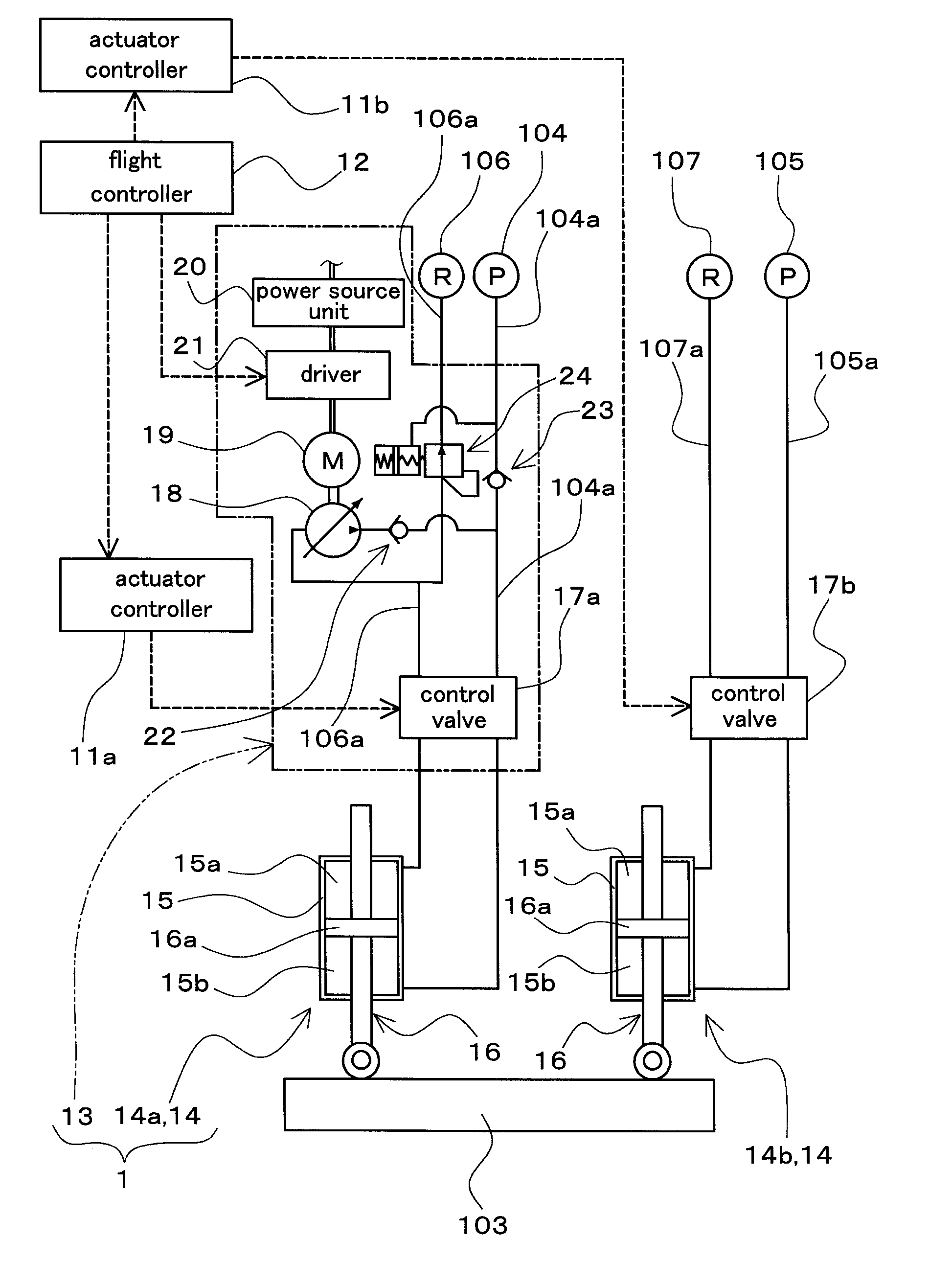
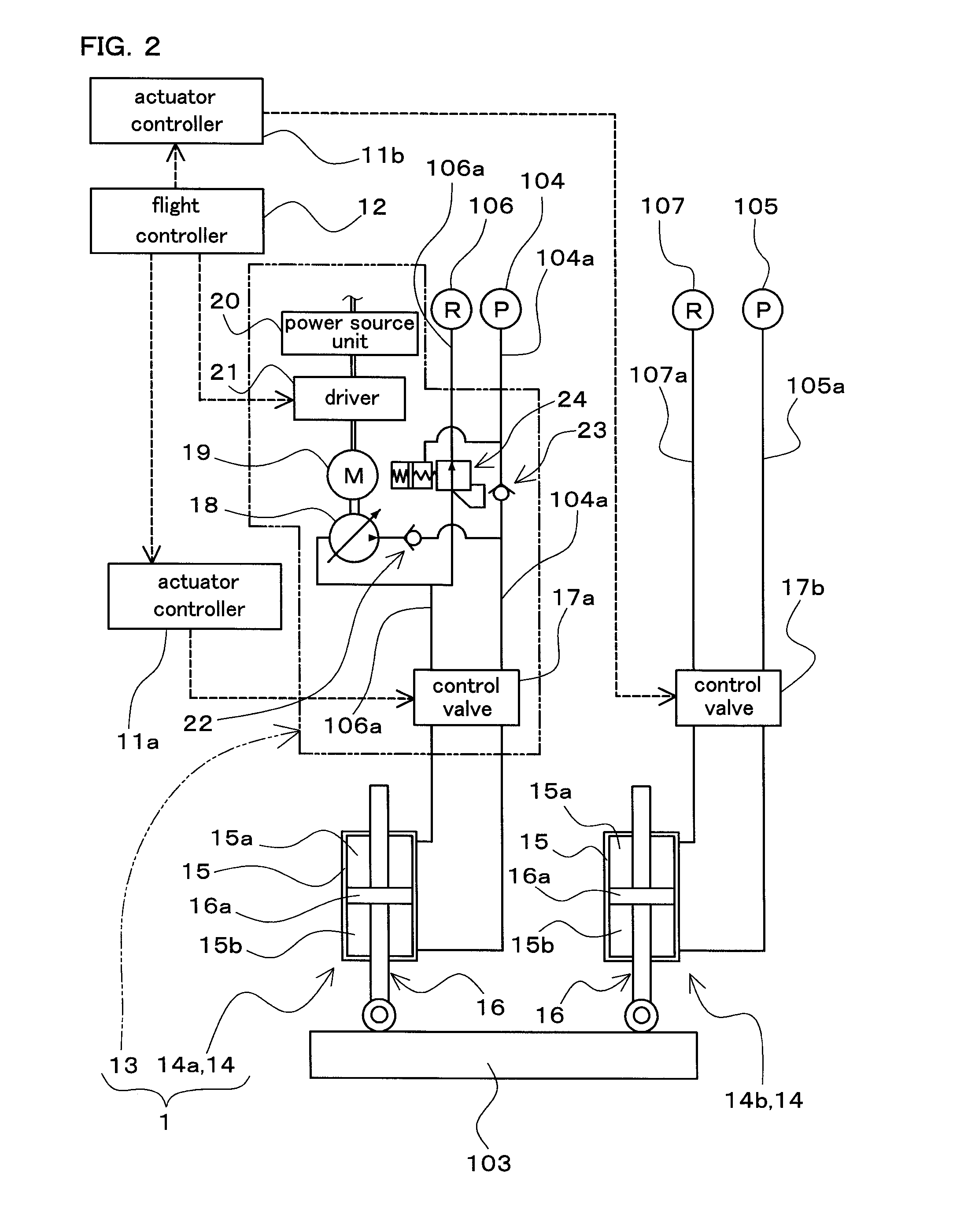
[0017]Hereinafter, an embodiment for carrying out the present invention will be described with reference to the accompanying drawings. It should be appreciated that an embodiment of the present invention can be widely applied as a hydraulic system for aircraft actuators that includes a hydraulically operated actuator for driving a control surface of an aircraft and that supplies pressure oil to the actuator.

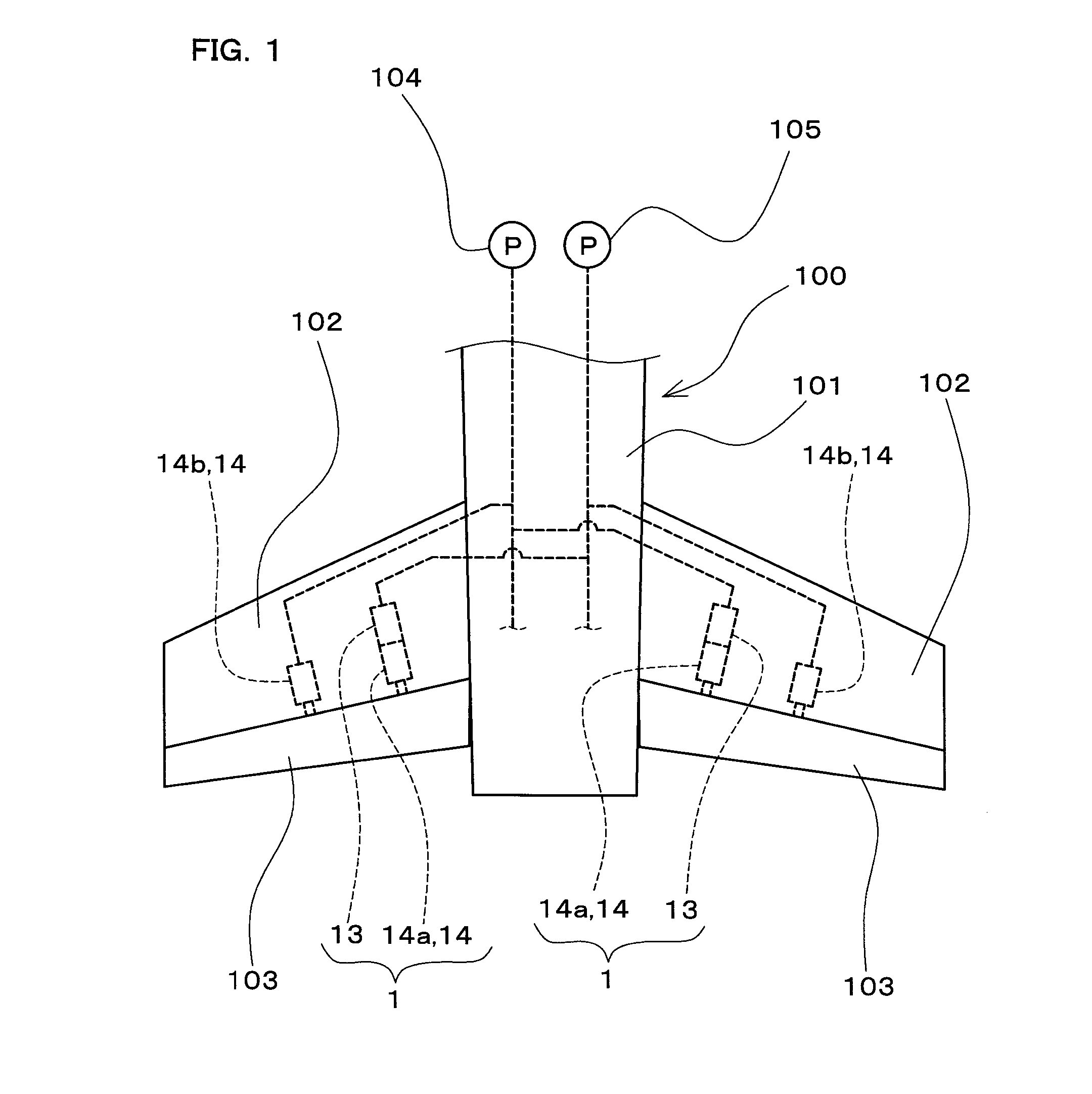
[0018]FIG. 1 is a diagram schematically showing part of an aircraft 100 to which a hydraulic system 1 for aircraft actuators (hereinafter, also simply referred to as a “hydraulic system 1”) according to an embodiment of the present invention is applied, showing a rear part of a body 101 of the aircraft 100 and a pair of tailplanes (102). In FIG. 1, illustration of a vertical tail at the rear part of the body 101 is omitted.

[0019]Each of the two tailplanes (102) is provided with an elevator 103 as a moving surface (flight control surface) constituting a control surface of the airc...


PUM


Abstract

An electric motor drives a variable capacity backup hydraulic pump that can supply pressure oil to an actuator when a loss or reduction occurs in the function of an aircraft central hydraulic power source. A power source unit rectifies electric power supplied from a variable frequency supply. A driver supplies the electric power from the power source unit, and drives the electric motor so as to rotate the pump at a predetermined constant rotational speed. The constant rotational speed is set, based on the change in the efficiency of each of the pump, the electric motor, and the driver with respect to the rotational speed of the pump, such that the overall efficiency, obtained as a product of these efficiencies, has a maximum value.

Description

CROSS-REFERENCE TO RELATED APPLICATIONS[0001]This application claims priority to Japanese Patent Application No. 2010-120328. The entire disclosure of Japanese Patent Application No. 2010-120328 is hereby incorporated herein by reference.BACKGROUND OF THE INVENTION[0002]1. Field of the Invention[0003]The present invention relates to a hydraulic system for aircraft actuators that includes a hydraulically operated actuator for driving a control surface of an aircraft and that supplies pressure oil to the actuator.[0004]2. Description of Related Art[0005]An aircraft is provided with control surfaces that are formed as moving surfaces (flight control surfaces) and are configured as an aileron, an elevator, and the like. A hydraulically operated actuator is often used as an actuator for driving such control surfaces. Further, pressure oil is supplied to such an actuator from an aircraft central hydraulic power source. However, a loss or reduction in the function (pressure oil supply func...

Claims


Application Information

Patent Timeline
Patent Type & Authority Applications(United States)
IPC IPC(8): F04B49/00
CPCB64C13/40F04B49/06F15B18/00F15B20/004F15B2211/20515Y02T50/44F15B2211/7054F15B2211/8633F15B2211/8636F15B2211/864F15B2211/8757F15B2211/20546B64C13/505Y02T50/40Y10T137/85986
Inventor FUKUI, ATSUSHISHIRAI, YASUYUKI
Owner NABLESCO CORP
Why Eureka
Try Eureka