Apparatus Having Scanner Lens for Material Processing by way of Laser

Inactive Publication Date: 2011-12-01
SCANSONIC MI
View PDF8 Cites 5 Cited by
  • Summary
  • Abstract
  • Description
  • Claims
  • Application Information

AI Technical Summary

Benefits of technology

[0029]Furthermore, during the measuring operation, the projector can also be actively positionable in the longitudinal direction of the weld by means of one or several separate degrees of freedom of the projector. This makes it possible to keep variable the advance between the measuring light lines from the projector and the la

Problems solved by technology

With conventional scanner optics, however, the accuracy of the laser spot that can be achieved when working the workpiece is relatively low.
While the vector of the relative speed can still be determined comparatively accurately, determining the position of the scanner optic relative to the workpiece is extremely inaccurate, due to elastic distortions of the arrangement, the limited resolution of the path sensors of the guide machine, manufacturing tolerances of the workpieces, and position deviations of the workpiece caused by the clamping device.
Errors from the scanner optics, due primarily to the limited dynamics of the drives and the limited resolution of the path sensors, increase the inaccuracy.
The distance between the workpiece and the scanner optics can be great, in which case, small changes or deviations in t

Method used


Image

  • Apparatus Having Scanner Lens for Material Processing by way of Laser
  • Apparatus Having Scanner Lens for Material Processing by way of Laser
  • Apparatus Having Scanner Lens for Material Processing by way of Laser

Examples


Embodiment Construction

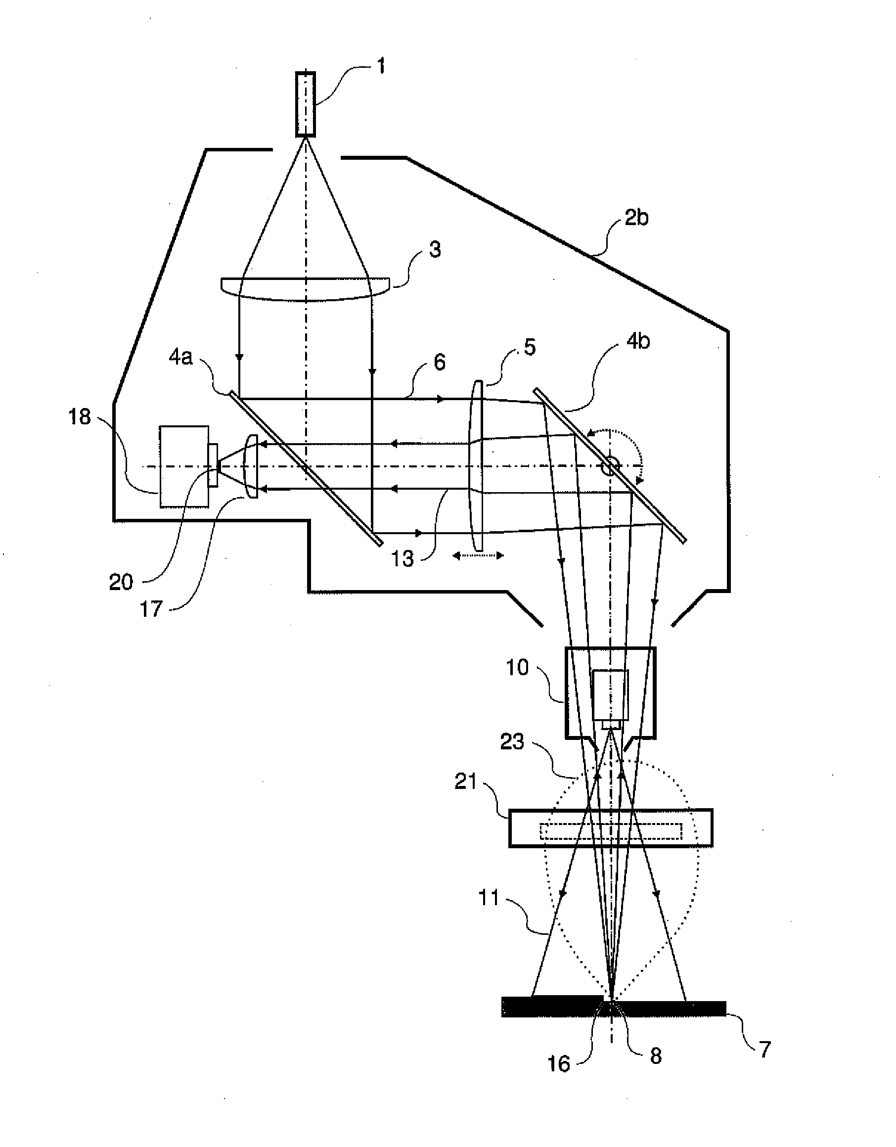
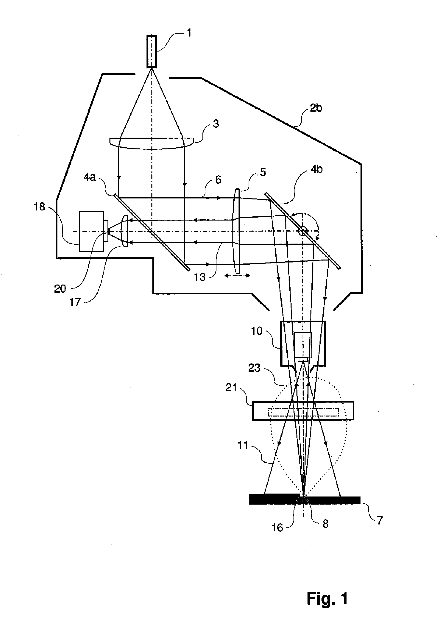
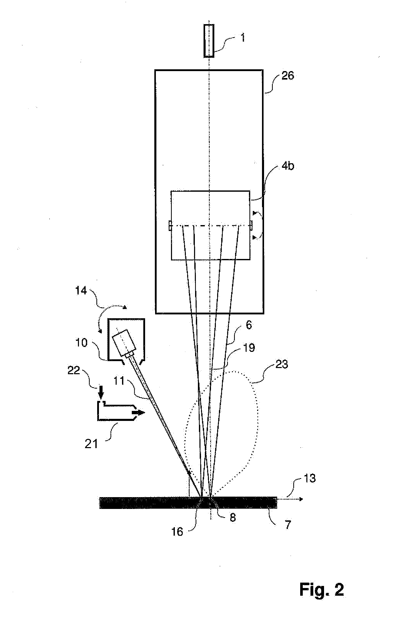
[0035]FIGS. 1 to 3 are schematic illustrations of a device 100 with a scanner optic for processing a workpiece using a laser as the processing tool. Scanning optic devices are typically mounted on a guide machine or tool carriage that moves the scanning optic, along with the processing tool, relative to the workpiece. This technology is known and is not described herein.

[0036]The device 100 according to the invention comprises a workpiece processing laser 1, scanner optics 2b, and a measuring system. The scanner optics 2b guides a workpiece processing beam 6 onto a workpiece 7. In the embodiments described herein, the workpiece processing beam or laser tool 1 is used to create a weld on the workpiece 7, but it is understood that the intended use of the device 100 described herein is not limiting and that the device may be used for other processes. The measuring system, described below in more detail, provides data relating to the geometry and other properties of the processing path,...


PUM

PropertyMeasurementUnit
Temperatureaaaaaaaaaa
Lengthaaaaaaaaaa
Speedaaaaaaaaaa

Abstract

The invention is a device for guiding a laser tool for processing a workpiece and includes a scanner optic, an image sensor that is optically integrated into a portion of the beam path of a workpiece processing beam, and at least one projector that is mounted externally to the scanner optics. Scanner optic, projector, and image sensor move together. The projector projects a second laser beam onto the workpiece. A semi-permeable deflection unit in the scanner optic is permeable to the second laser beam and impermeable to the workpiece processing beam. The image sensor is arranged on the side of the semi-permeable deflection unit facing away from the path of the workpiece processing beam. The measuring light is reflected from the workpiece into the scanner optic, through the semi-permeable deflection unit and then detected by the image sensor. The device enables mass production of fine fillet welds and flange welds.

Description

[0001]This application is a continuation of PCT / DE2010 / 000057, filed on Jan. 21, 2010, and claims priority from German applications DE 10 2009 008 126.7, filed on Feb. 9, 2009, and DE 10 2009 057 209.0, filed on Nov. 27, 2009, both of which are incorporated herein in their entirety.BACKGROUND INFORMATION[0002]1. Field of the Invention[0003]The invention relates to a device equipped with scanner optics configured for pre- or post-objective scanning for use with laser-processing of materials or workpieces, and particularly, for laser welding.[0004]2. Discussion of the Prior Art[0005]It is known to use scanner optics with deflection units to precisely guide a laser beam. Mirrors are customarily used as deflection units. Considerably higher speed and acceleration variables can be achieved with the scanner optics than with guide machines. Such scanning optics also allow seams and contours to be scribed onto the workpieces that are to be processed during the travel motion of the guide mac...

Claims


Application Information

Patent Timeline
IPC IPC(8): H05B7/18
CPCB23K26/045B23K26/14B23K26/0807B23K26/044B23K26/082
Inventor SIEVI, PRAVIN
Owner SCANSONIC MI
Why Eureka
Try Eureka