Head tracking

a head tracking and head technology, applied in the direction of linear/angular speed measurement, digital computer details, instruments, etc., can solve the problems of accumulating errors, changing the reference direction, and fixing the sound source image relative to the earth is therefore unsuitable, so as to reduce the stationary distortion of the magnetic reference field, simplify the calculation of rotation angle, and facilitate the orientation of the coil

Active Publication Date: 2011-12-01
KONINKLIJKE PHILIPS ELECTRONICS NV
View PDF11 Cites 72 Cited by
  • Summary
  • Abstract
  • Description
  • Claims
  • Application Information

AI Technical Summary

Benefits of technology

[0019]In a further embodiment, the magnetic transmitter comprises two orthogonal coils placed in a transverse plane, wherein the magnetic field of each of the two orthogonal coils is modulated with different modulation frequencies. Preferably, a first coil is placed in a left-right direction and a second coil in a front-back direction. In such a way two magnetic fields with different orientations are created, which enables the magnetic sensor to discern orientation relative to the two coils e.g. by means of ratios between observed field strengths, instead of responding to absolute field strengths. Thus, the method becomes more robust to absolute field strength variations as could e.g. result from varying the distance to the transmitter.
[0020]Having magnetic fields of the two orthogonal coils modulated with different modulation frequencies is especially advantageous for suppressing stationary distortions of the magnetic reference field due to nearby ferromagnetic materials such as posts, chairs, train coach constructions etc., or transmissive materials such as e.g. clothing worn over the magnetic transmitter or the magnetic sensor. The magnetic field can be modulated with a relatively high frequency, preferably in a frequency range of 20-30 kHz, so that fluctuations outside this frequency band, such as slow variations resulting from the aforementioned external influences, are suppressed. Additional advantage of the present embodiment is that by choosing different modulation frequencies for both coils of the magnetic transmitter, and by using selective filtering to these frequencies on the received magnetic field in the magnetic sensor it is possible to sense the head direction in a two dimensions with the magnetic sensor comprising a single coil.
[0021]In a further embodiment, the magnetic sensor comprises a coil, wherein the coil is placed in a predetermined direction of the head of the user. This is a convenient orientation of the coil, as it simplifies calculation of the rotation angle.

Problems solved by technology

However, when the walking or running user takes a turn his body undergoes a change of position (to a tilt), which especially when long lasting, should cause a change of the reference direction.
Fixing a sound source image relative to earth is hence not desirable.
This in turn results in errors accumulated over time, and leads to an annoying stationary position bias of the virtual sound sources.

Method used


Image

  • Head tracking
  • Head tracking
  • Head tracking

Examples


Embodiment Construction

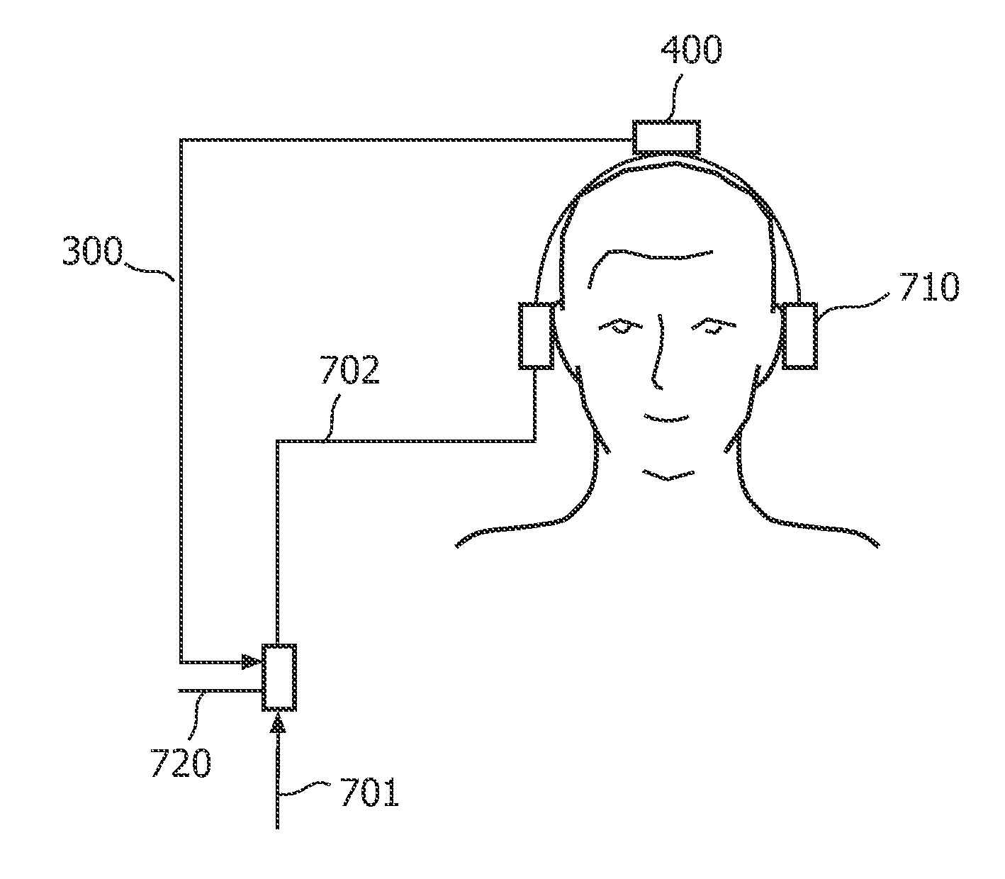
[0035]The present invention relates to head tracking that is suitable for applying to headphone reproduction for creating a realistic out-of-head illusion.

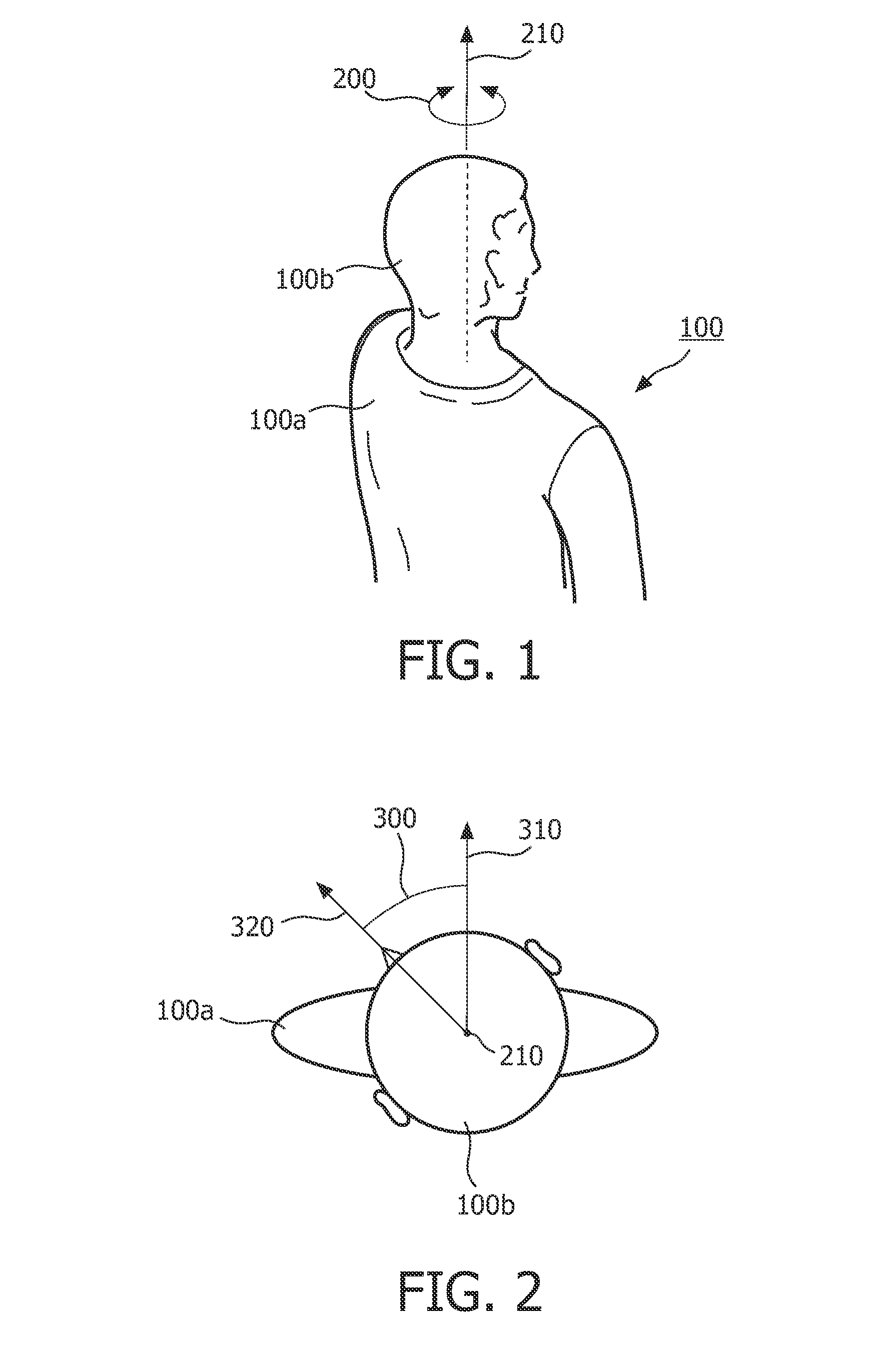
[0036]FIG. 1 illustrates a head rotation. A user body 100 is depicted with a body torso 100a and a head 100b. The axis 210 is the head rotation axis. The rotation itself is depicted by an arrow 200.

[0037]FIG. 2 shows a rotation angle 300 of a head 100b of a user with respect to a reference direction 310. The view of the user 100 from a top is depicted. A direction 310 is assumed to be the forward direction of the body torso 100a, which is also assumed to be a neutral direction of the head 100b. The forward body direction is then determined as direction having as reference the user shoulders and facing the direction in which the user face is pointing. This forward body direction is determined whatever the position of the user body is, e.g. whether the user is lying down or half sitting half lying in a relaxation chair. In the remai...


PUM


Abstract

A head tracking system (400) is proposed in the present invention that determines a rotation angle (300) of a head (100b) of a user (100) with respect to a reference direction (310), which is dependent on a movement of a user (100). Here the movement of a user should be understood as an act or process of moving including e.g. changes of place, position, or posture, such as e.g. lying down or sitting in a relaxation chair. The head tracking system according to the invention comprises a sensing device (410) for measuring a head movement to provide a measure (401) representing the head movement, and a processing circuit (420) for deriving the rotation angle of the head of the user with respect to the reference direction from the measure. The reference direction (310) used in the processing circuit (420) is dependent on the movement of the user. The advantage of making the reference direction (310) dependent on a movement of a user is that determining the rotation angle (300) of the head (100b) is independent of the environment, i.e. not fixed to environment. Hence whenever the user (100) is e.g. on the move and his body parts undergo movement the reference direction is adapted to this movement.

Description

FIELD OF THE INVENTION[0001]The invention relates to a head tracking system. The invention also relates to a head tracking method. Furthermore, the invention relates to an audio reproduction system.BACKGROUND OF THE INVENTION[0002]Headphone reproduction of sound typically provides an experience that a sound is perceived ‘inside the head’. Various virtualization algorithms have been developed which create an illusion of sound sources being located at a specific distance and in a specific direction. Typically, these algorithms have an objective to approximate a transfer function of the sound sources (e.g. in case of stereo audio, two loudspeakers in front of the user) to the human ears. Therefore, virtualization is also referred to as binaural sound reproduction.[0003]However, merely applying a fixed virtualization is not sufficient for creating a realistic out-of-head illusion. A human directional perception appears to be very sensitive to head movements. If virtual sound sources mov...

Claims


Application Information

Patent Timeline
Patent Type & Authority Applications(United States)
IPC IPC(8): G06F15/00G01P3/00H04R25/00
CPCH04S7/304
Inventor DILLEN, PAULUS HENRICUS ANTONIUSOOMEN, ARNOLDUS WERNER JOHANNESSCHUIJERS, ERIK GOSUINUS PETRUS
Owner KONINKLIJKE PHILIPS ELECTRONICS NV
Why Eureka
Try Eureka