Power storage device

a power storage device and power technology, applied in the field of power storage devices, can solve problems such as unexpected potential, and achieve the effect of high discharge voltage and high energy density

Active Publication Date: 2011-12-01
SEMICON ENERGY LAB CO LTD
View PDF6 Cites 32 Cited by
  • Summary
  • Abstract
  • Description
  • Claims
  • Application Information

AI Technical Summary

Benefits of technology

[0029]According to one embodiment of the disclosed invention, a power storage

Problems solved by technology

However, even when a positive electrode active material which includes a phosphate compound having an ol

Method used


Image

  • Power storage device
  • Power storage device
  • Power storage device

Examples


embodiment 1

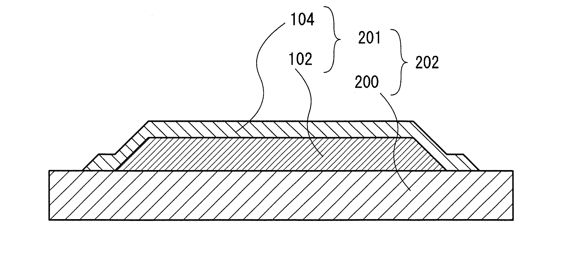
[0043]In this embodiment, a structure of a positive electrode included in a power storage device according to one embodiment of the present invention will be described with reference to FIG. 1.

[0044]FIG. 1 is a schematic cross-sectional view of a positive electrode included in a power storage device which is one embodiment of the present invention.

[0045]As illustrated in FIG. 1, in this embodiment, a positive electrode active material layer 201 includes a film-form first region which includes a compound containing lithium and nickel (hereinafter, this region is referred to as a first region 102); and a film-form second region which includes a compound containing lithium and one or more of iron, manganese, and cobalt, but not containing nickel (hereinafter, this region is referred to as a second region 104). The first region 102 is covered with the second region 104.

[0046]That is, a top surface and a side surface of the film-form first region 102 which includes the compound containin...

embodiment 2

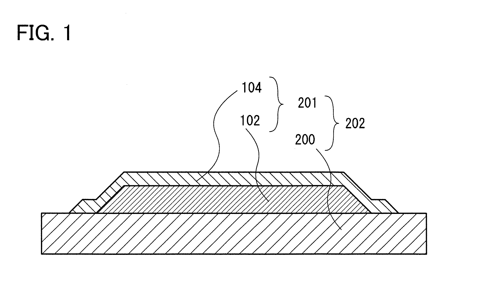
[0060]In this embodiment, a structure of a positive electrode included in a power storage device according to one embodiment of the present invention, which is a different example from the example illustrated in FIG. 1, will be described with reference to FIG. 2, FIG. 3, and FIG. 4.

[0061]FIG. 2, FIG. 3, and FIG. 4 are each a schematic cross-sectional view of a positive electrode included in a power storage device which is one embodiment of the present invention.

[0062]As illustrated in FIG. 2, in this embodiment, the positive electrode active material layer 201 includes the film-form first region 102 which includes a compound containing lithium and nickel; and the film-form second region 104 which includes a compound containing lithium and one or more of iron, manganese, and cobalt, but not containing nickel. The first region 102 is covered with the second region 104. A top surface and a side surface of the first region 102 are covered with the second region 104. In addition, the sec...

embodiment 3

[0065]In this embodiment, a method for forming a positive electrode included in a power storage device which is one embodiment of the present invention will be described below.

[0066]First, the positive electrode current collector 200 is prepared (FIG. 5A).

[0067]There is no particular limitation on a material used for the positive electrode current collector 200; however, a material having high conductivity such as platinum, aluminum, copper, or titanium can be used. In this embodiment, titanium is used.

[0068]Next, over the positive electrode current collector 200, the first region 102 is formed using a compound containing lithium and nickel (FIG. 5B).

[0069]As a method for forming the first region 102 including the compound containing lithium and nickel, a dry process such as a PVD method (e.g., a sputtering method), a vacuum evaporation method, or a CVD method (e.g., a plasma CVD method, a thermal CVD method, or an LPCVD method) can be used. By forming the first region 102 including...


PUM


Abstract

An object is to provide a power storage device with high discharge capacity and high energy density. The power storage device includes a positive electrode in which a positive electrode active material is formed over a positive electrode current collector; and a negative electrode which faces the positive electrode with an electrolyte interposed therebetween. The positive electrode active material includes a film-form first region which includes a compound containing lithium and nickel; and a film-form second region which includes a compound containing lithium and one or more of iron, manganese, and cobalt, but not containing nickel. The first region is covered with the second region. Since a superficial portion of the positive electrode active material does not contain nickel, nickel is not in contact with an electrolyte solution; thus, generation of a catalyst effect of nickel can be suppressed, and a high discharge potential of nickel can be utilized.

Description

BACKGROUND OF THE INVENTION[0001]1. Field of the Invention[0002]One embodiment of the disclosed invention relates to a power storage device.[0003]2. Description of the Related Art[0004]The field of portable electronic devices such as personal computers and cellular phones has progressed significantly. The portable electronic device needs a chargeable power storage device having high energy density, which is small, lightweight, and reliable. As such a power storage device, for example, a lithium-ion secondary battery is known. In addition, development of electrically propelled vehicles on which secondary batteries are mounted has also been progressing rapidly from a rise of growing awareness to environmental problems and energy problems.[0005]In a lithium-ion secondary battery, as a positive electrode active material, a phosphate compound having an olivine structure and containing lithium (Li) and iron (Fe), cobalt (Co), or nickel (Ni), such as lithium iron phosphate (LiFePO4), lithi...

Claims


Application Information

Patent Timeline
IPC IPC(8): H01M4/58H01M4/64H01M4/131H01M4/136H01M4/36H01M4/505H01M4/525
CPCH01M4/5805Y02E60/122Y02T10/7011H01M10/0525Y02E60/10H01M4/02H01M4/58H01M10/05Y02T10/70
Inventor KAWAKAMI, TAKAHIROYAMAKAJI, MASAKITAKAHASHI, NADINEYAMAZAKI, SHUNPEI
Owner SEMICON ENERGY LAB CO LTD
Why Eureka
Try Eureka