Method for testing pipeline welds using ultrasonic phased arrays

a phased array and pipeline technology, applied in the direction of magnetic property measurement, instruments, material analysis, etc., can solve the problems of restricted accuracy limits of these methods, and the general less suitable of compression waves (longitudinal waves)

Active Publication Date: 2011-12-08
SAIPEM SPA
View PDF2 Cites 69 Cited by
  • Summary
  • Abstract
  • Description
  • Claims
  • Application Information

AI Technical Summary

Benefits of technology

[0057]The method of the present invention has particular application when the pipes are pipes clad with a corrosion resistant alloy (CRA). The CRA may be in the form of stainless steel or a nickel alloy, for example. The material to be welded may therefore comprise austenitic material. The weld may therefore be considered as being an austenitic weld, in that the material welded

Problems solved by technology

International standards for NDT methods used in laying pipelines place strict limits on the accuracy of these methods.
Compression waves (longitudinal waves) are generally less suitable because t

Method used


Image

  • Method for testing pipeline welds using ultrasonic phased arrays
  • Method for testing pipeline welds using ultrasonic phased arrays
  • Method for testing pipeline welds using ultrasonic phased arrays

Examples


first embodiment

[0075]The method of non-destructive testing of the weld is performed solely by means of inspecting the weld joint with ultrasonic probes. An NOT method according to the invention will now be described with reference to FIG. 3.

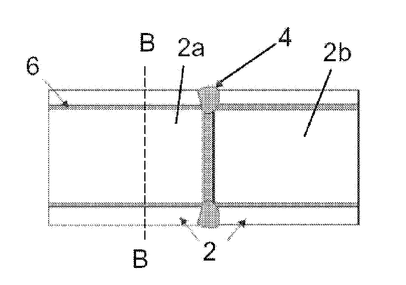
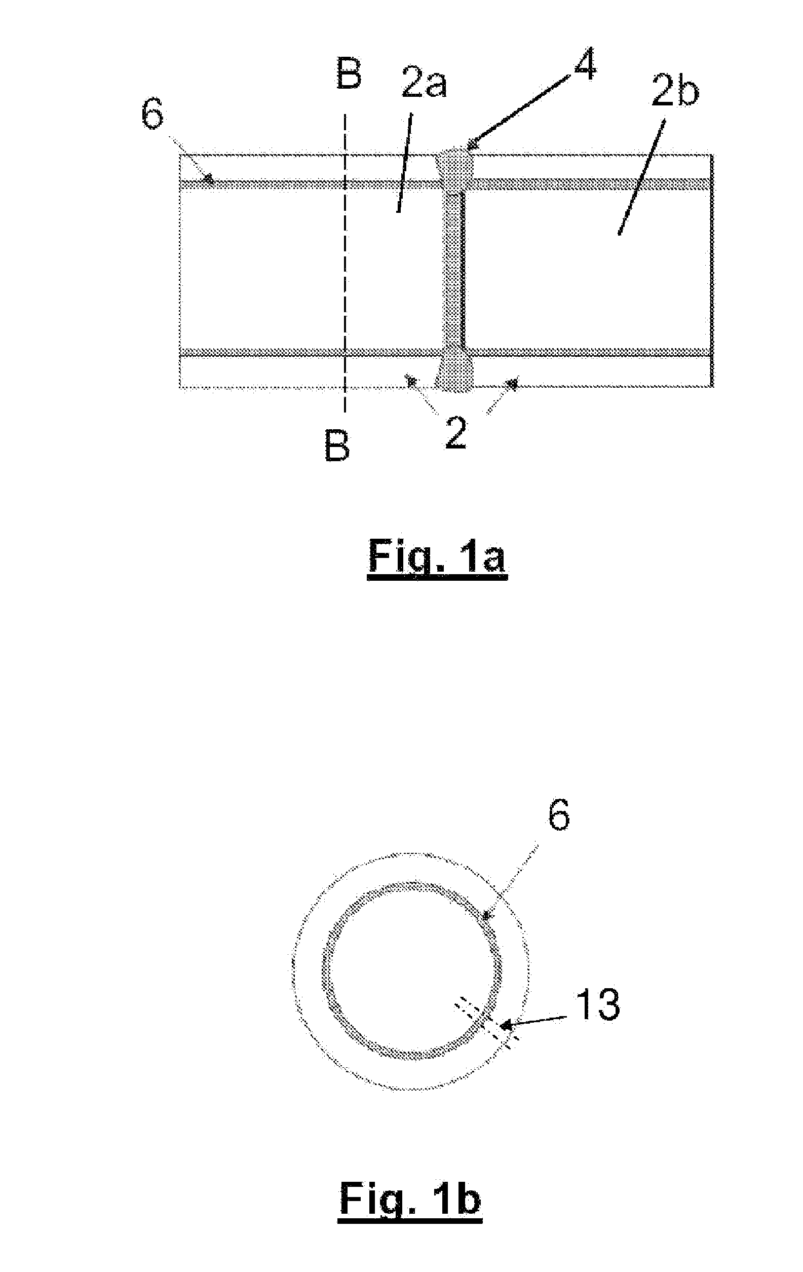
[0076]FIG. 3 shows two ultrasonic transducer arrays 8a, 8b used in the NDT method. The arrays 8a, 8b are arranged on the pipe sections 2 on opposite sides of the weld joint. Each array is in the form of a 90 mm phased array R / D Tech probe available from Olympus Corporation. The arrays operate at a frequency of about 4 MHz and are provided with a rexolyte wedge having an angle of about 21°. Each phased array unit 8a, 8b has two banks of 30 transducer elements. Thus with two phased array units 8a, 8b there are a total of 120 transducer elements, 60 upstream of the weld joint and 60 downstream. In addition to the phased array probes 8a, 8b there is also mounted ultrasonic probes 9a and 9b dedicated to generating surface waves 7. A further set of ultrasonic probes ...

second embodiment

[0096]In this second embodiment, the pipe has a diameter of about 300 mm, a wall thickness of about 22 mm+3 mm (cladding), and a bevel angle of about 8 degrees to the vertical.

[0097]The second embodiment utilises 126 transducer elements, 63 arranged upstream and 63 arranged downstream. Of those elements six individual transducer elements are provided (three upstream and three downstream) separately from the upstream and downstream phased arrays, which are each provided by 60 elements. The transducer elements scan the weld and produce measurements on about 50 separate measurement channels. The elements of the phased arrays are able, by means of operating under different focal laws, to emit ultrasonic beams at angles varying from 45 to 70 degrees (in this case the angle being 90 degrees when perpendicular to the surface and 0 degrees when parallel). Surface waves are also able to be transmitted. For non-surface wave inspections, the path length of the radiation may range from about 10...

third embodiment

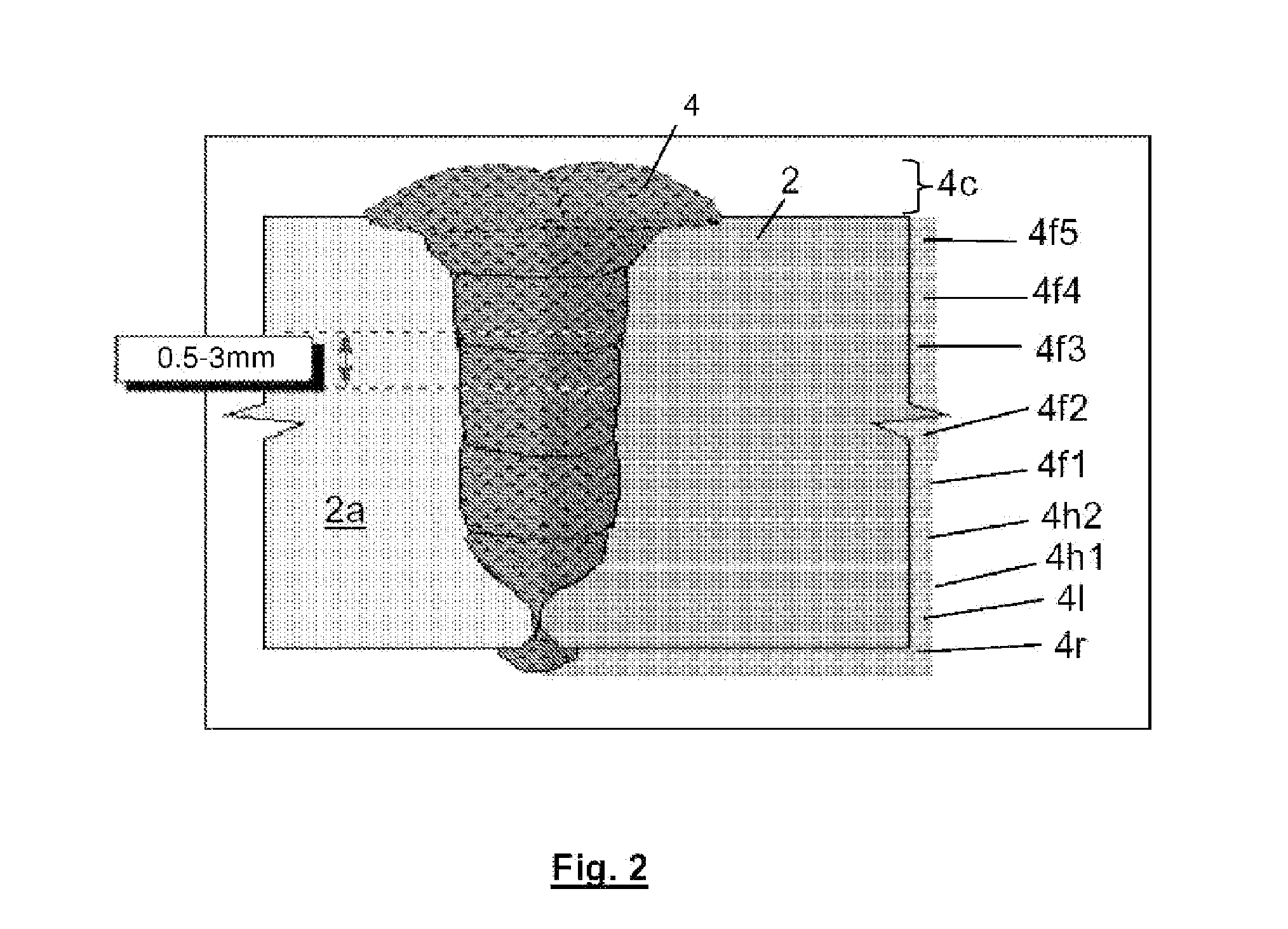
[0103]FIG. 5 shows a calibration block for use in the invention. The block includes machined holes at the bottom of each of which there is a flat bottomed hole. The face of the flat bottomed hole is aligned with the geometry of the bevel and acts as a reflector, simulating a defect of a known shape and size. The block also includes notches 14cn1, 14cn2, 14cn3, 14rn1, 14rn2, 14rn3 in the cap and root regions, simulating defects near the inner and outer pipe diameters. The various reference numerals used in FIG. 5 are summarised as follows:

Cap Notches 1 to 314cn1, 14cn2, 14cn2Cap14cFill layers 1 to 714f1 to 14f7Hot Pass14hRoot14rRoot Notches 1 to 314rn1, 14rn2, 14rn3

[0104]The calibration block is used to generate a look-up table for use when performing NDT inspections on a pipe having a bevel geometry and material composition corresponding to that of the calibration block. For each measurement made during the NDT method, a reflector is provided in the calibration block to simulate a d...


PUM


Abstract

NDT inspection of an austenitic weld between two CRA Clad pipes using a phased ultrasonic transducer array system is described. The method may be performed during laying of gas/oil fatigue sensitive pipelines, for example, at sea. Two types of UT inspection may be generated simultaneously by a Phased Array on each side (Upstream and Downstream) of a girth weld. Firstly, mode converted longitudinal waves are used. These waves have properties that they propagate well. Shear waves are also used. The combination of these two ultrasonic waves, with the addition of surface waves, enables 100% of the girth weld to be inspected to the standard required in fatigue sensitive welds, such as Steel Catenary Risers. Shear waves and compression waves are emitted substantially contemporaneously. Defects may be detected and measured using time of flight information and amplitudes of radiation detected on reflection and on diffraction from the defect.

Description

BACKGROUND OF THE INVENTION[0001]The present invention concerns a method for inspecting welds between pipe sections when laying pipelines. More specifically, but not exclusively, this invention relates to a method for the non-destructive inspection of welds between pipe sections using a phased ultrasonic transducer array system.[0002]The present invention is particularly, but not exclusively, concerned with a non-destructive weld testing method used when laying oil or gas pipelines underwater. When laying a pipeline at sea it is customary to weld, on a lay-barge, individual pipe sections to a pipe string (the pipe string leading towards the seabed). The welding process takes place on the lay-barge. The pipe-string, when being laid, is under great tension and weld joints must be sufficiently strong to withstand the high forces imposed on them. As such, each time a pipe is welded to another pipe, extensive tests are made to ensure that the quality of the weld joint formed is sufficien...

Claims


Application Information

Patent Timeline
IPC IPC(8): G01N29/00
CPCG01N29/043G01N29/262G01N2291/2675G01N2291/106G01N2291/2634G01N29/4445
Inventor CATALDO, GIUSEPPINADILIGENT, OLIVIER
Owner SAIPEM SPA
Why Eureka
Try Eureka