Method of navigating a spinning, artificial satellite and controlling the global, terrestrial surveillance coverage thereof

Inactive Publication Date: 2011-12-08
JOHNSON KARA WHITNEY +1
View PDF13 Cites 17 Cited by
  • Summary
  • Abstract
  • Description
  • Claims
  • Application Information

AI Technical Summary

Benefits of technology

[0017]The low-light-level EBCMOS optical sensor uses the feature of Electronic Bombardment (EB) in which a local high voltage provides a gain greater than 100, i.e., 100 electrons output per each photon at the photocathode. This high gain enables the “thinning” of the photocathode—thus reducing the bulk of material where deleterious radiation effects occur. The lost sensitivity at the photocathode is recovered with the extremely high gain, resulting in superior sensitivity, noise performance, bandwidth capability, and other sensor performance measures.
[0018]The present invention also uses a radii-squared histogram algorithm to measure a radius parameter that is independent of any angular smearing effect that would occur only in the tangential direction if there were any smearing effect in the small-angle, e.g., two-degree, field-of-view during the relatively slow 20 RPM spin rate. The relatively high sampling rate of the high gain EBCMOS optical sensor further mitigates the smearing effect as does the averaging of a multiplicity of radii-squared measurements over the three-second rotation measurement period.
[0019]The present invention additionally provides real-time, near-autonomous, accurate navigation of the satellite and bro

Problems solved by technology

Additionally, as mentioned above, with regard to reliability of the implementation of space-based instrumentation, additional critical issues t

Method used


Image

  • Method of navigating a spinning, artificial satellite and controlling the global, terrestrial surveillance coverage thereof
  • Method of navigating a spinning, artificial satellite and controlling the global, terrestrial surveillance coverage thereof
  • Method of navigating a spinning, artificial satellite and controlling the global, terrestrial surveillance coverage thereof

Examples


Example

[0045]U.S. application Ser. No. 12 / 363,959 filed on Feb. 2, 2009 entitled METHOD OF DETERMINING AND CONTROLLING THE INERTIAL ATTITUDE OF A SPINNING, ARTIFICIAL SATELLITE AND SYSTEMS THEREFOR and U.S. application Ser. No. 11 / 818,723 filed Jun. 15, 2007, now U.S. Pat. No. 7,739,003, entitled METHOD OF DETERMINING AND CONTROLLING THE INERTIAL ATTITUDE OF A SPINNING, ARTIFICIAL SATELLITE AND SYSTEMS THEREFOR are hereby incorporated by reference herein.

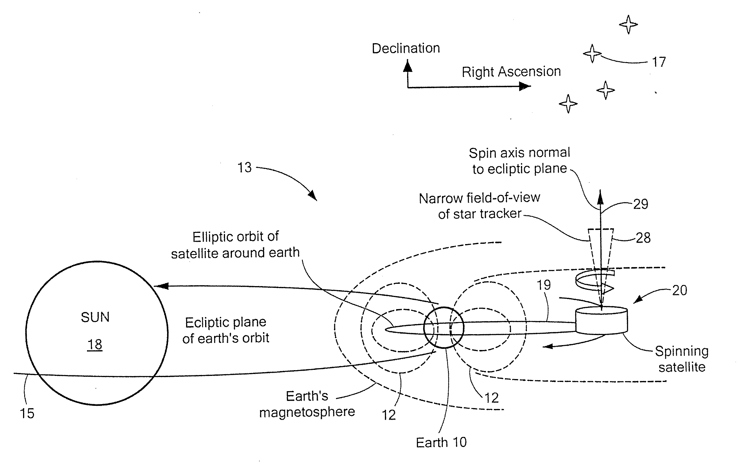
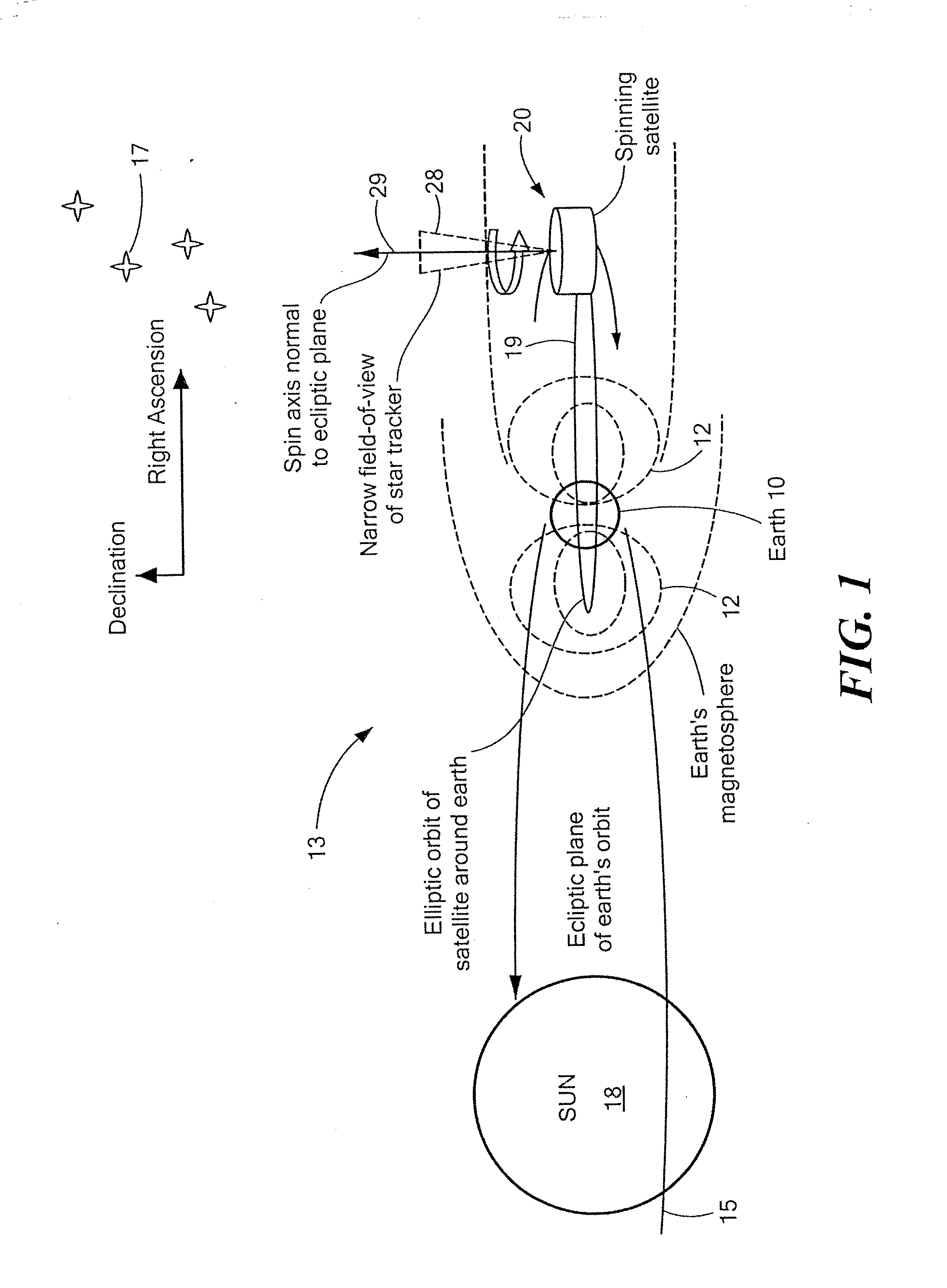
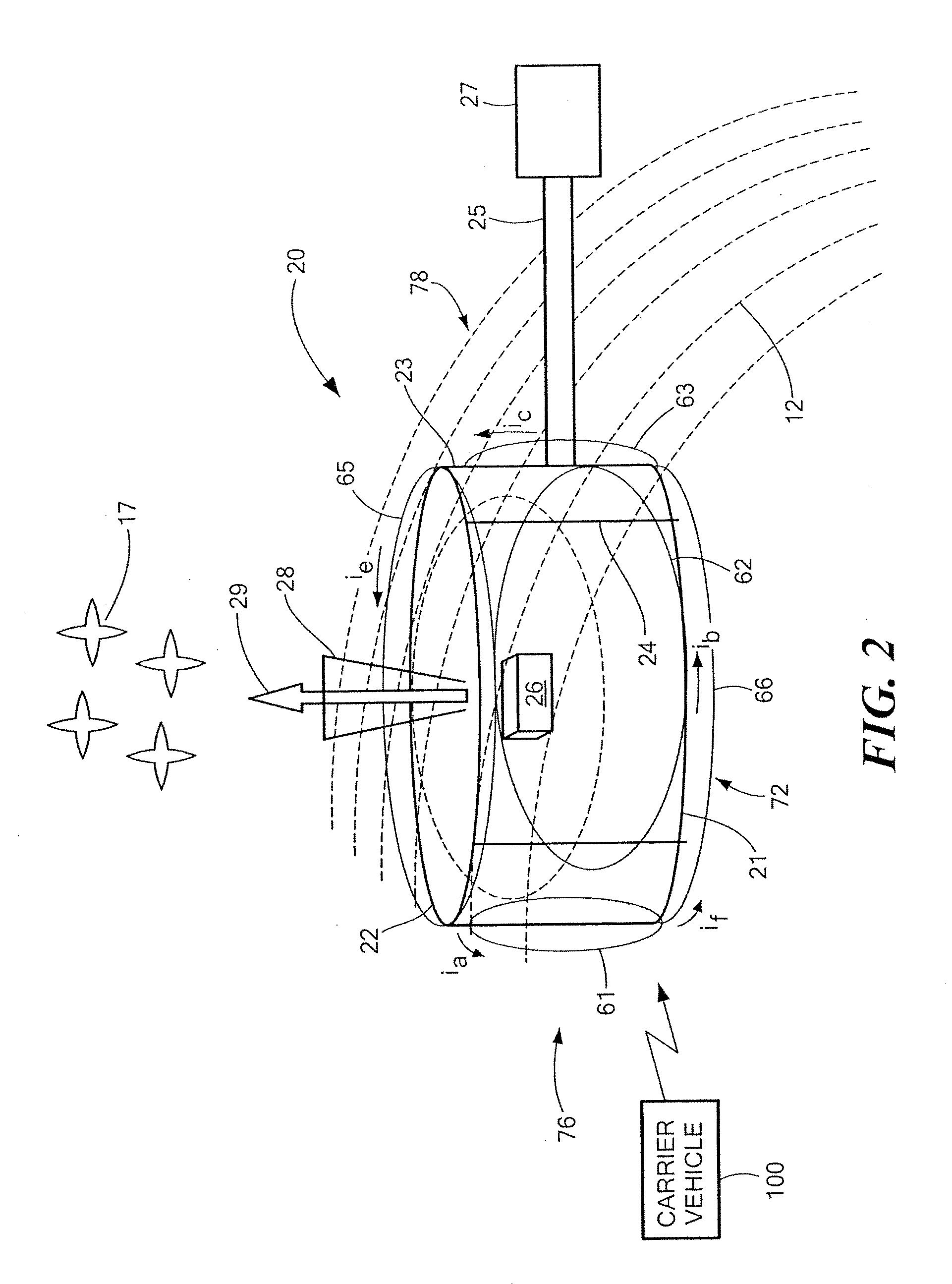
[0046]Methods and systems for accurately determining and controlling the inertial attitude of an artificial satellite, a spinning satellite, a spinning strategic missile, a spinning communication antenna system, a spinning surveillance satellite system, a spinning station-keeping formation system, a spinning scientific measurement satellite system, a spinning astronomical measurement satellite system, and the like (hereinafter, collectively referred to as “an artificial satellite” for brevity) are disclosed. The disclosed methods constitut...


PUM


Abstract

A method of controlling inertial attitude of an artificial satellite in order to perform a navigation function and to maximize terrestrial coverage of the Earth by the satellite. The method includes deploying the artificial satellite in an orbit about the poles of the Earth; applying gyroscopic precession to the artificial satellite spin axis to precess and maintain the satellite near the ecliptic pole; deploying the artificial satellite so that the spin axis is initially perpendicular to or substantially perpendicular to sun lines; and applying gyroscopic precession to the artificial satellite spin axis to precess the spin axis away from an initial deployed attitude at a selectively-variable precession rate and to maintain the spin axis perpendicular to or substantially perpendicular to a the sun lines.

Description

CROSS REFERENCE TO RELATED APPLICATIONS[0001]This application is a continuation-in-part of U.S. application Ser. No. 12 / 363,959 filed on Feb. 2, 2009 entitled METHOD OF DETERMINING AND CONTROLLING THE INERTIAL ATTITUDE OF A SPINNING, ARTIFICIAL SATELLITE AND SYSTEMS THEREFOR, which is a continuation-in-part of U.S. application Ser. No. 11 / 818,723 filed Jun. 15, 2007, now U.S. Pat. No. 7,739,003 and entitled METHOD OF DETERMINING AND CONTROLLING THE INERTIAL ATTITUDE OF A SPINNING, ARTIFICIAL SATELLITE AND SYSTEMS THEREFOR, which claims the benefit of priority through U.S. Provisional Application No. 60 / 815,068 filed Jun. 20, 2006.STATEMENT REGARDING FEDERALLY SPONSORED RESEARCH OR DEVELOPMENT[0002](Not applicable)BACKGROUND OF THE INVENTION[0003]The present invention relates to the field of guidance, navigation, and control avionics, and, more particularly, to devices, systems, and methods for controlling the inertial attitude of an artificial, spinning satellite so as to support an...

Claims


Application Information

Patent Timeline
IPC IPC(8): B64G1/28B64G1/66
CPCB64G1/281B64G1/32B64G1/361B64G1/363B64G1/365B64G1/242G01S3/7862G01S3/7867G05D1/0883B64G1/1007B64G1/1085B64G1/44B64G1/244
Inventor JOHNSON, WILLIAM M.
Owner JOHNSON KARA WHITNEY
Why Eureka
Try Eureka