Battery heating apparatus for vehicle

a technology for heating apparatus and batteries, which is applied in the direction of battery/fuel cell control arrangement, electric devices, electrochemical generators, etc., can solve the problems of adversely affecting the size of the device, increasing the size and complexity of the device, and unable to achieve effective heating of the battery, so as to achieve the effect of efficient heating of the battery and adversely affecting the size of the apparatus

Inactive Publication Date: 2011-12-08
HONDA MOTOR CO LTD
View PDF4 Cites 85 Cited by
  • Summary
  • Abstract
  • Description
  • Claims
  • Application Information

AI Technical Summary

Benefits of technology

[0008]An object of this invention is therefore to overcome the foregoing drawbacks by providing a battery heating apparatus for a vehicle, which apparatus can efficiently heat a battery so that the battery can output expected power, without adversely affecting the size of the apparatus.

Problems solved by technology

However, in the configuration of '581, since the heat is transferred from the outside of the battery, the heating efficiency is low and also the additionally-installed heater results in the increase in size and complexity of the device, unfavorably.
Further, when the configuration to heat the battery using the direct-current power stored in the capacitor is applied as in '628, large capacitance of the capacitor is required and it adversely affects the size of the device.
In addition, since it utilizes the ripple current generated upon the switching control, in the case of low-frequency switching, again the large capacitance of the capacitor is required because charge transfer corresponding to voltage fluctuation of the capacitor plays a main role for the heating, whilst in the case of high-frequency switching, amplitude of the ripple current is small and heat generation of internal resistance of the battery is not enough accordingly, so that the effective heating of the battery can not be achieved, disadvantageously.

Method used


Image

  • Battery heating apparatus for vehicle
  • Battery heating apparatus for vehicle
  • Battery heating apparatus for vehicle

Examples


first embodiment

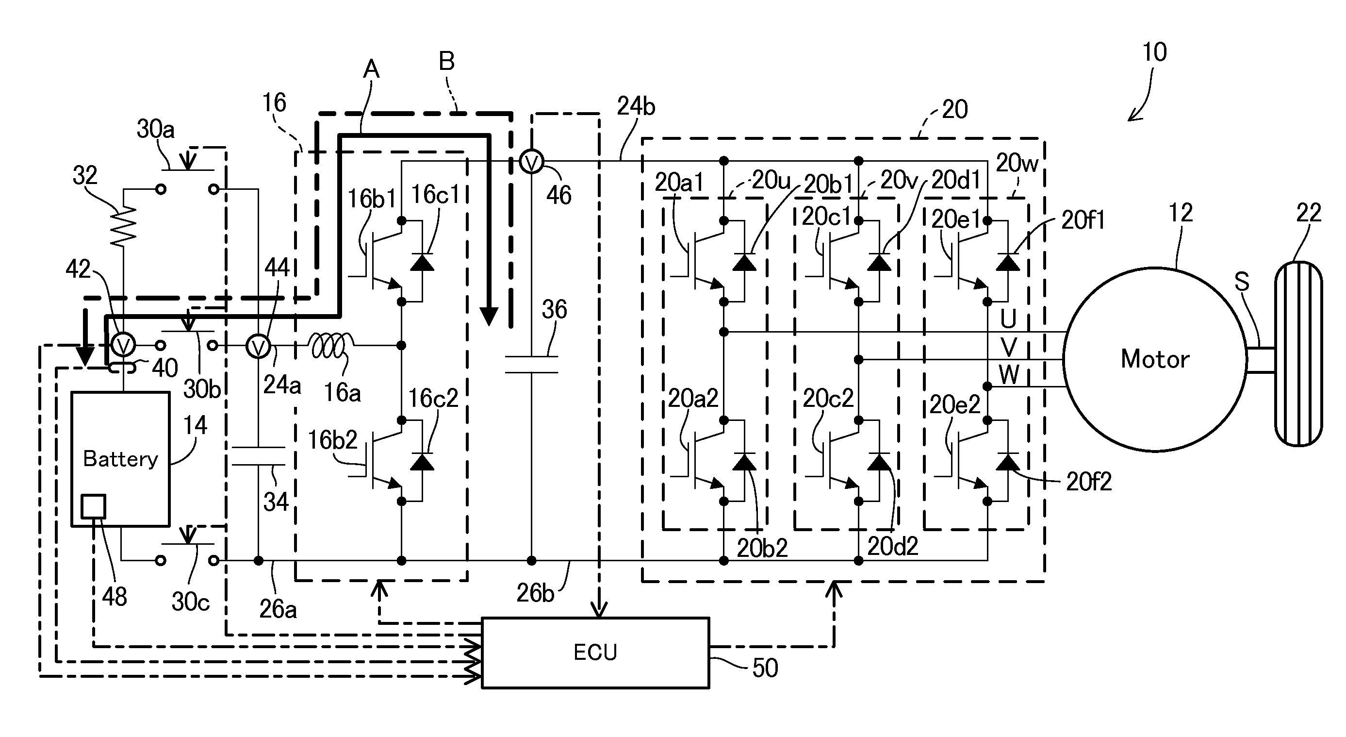
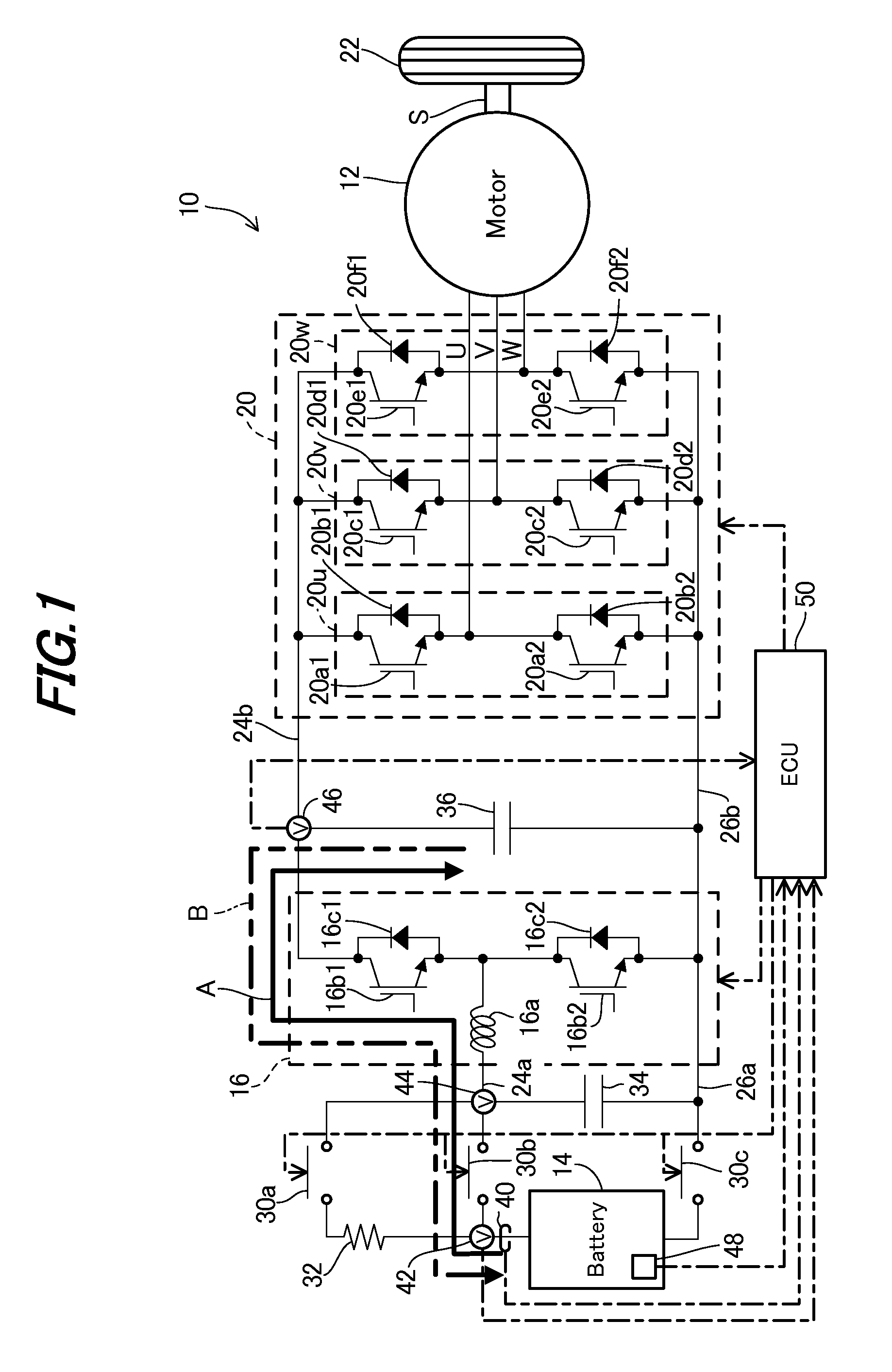
[0020]FIG. 1 is an overall view schematically showing a battery heating apparatus for a vehicle according to this invention.

[0021]In FIG. 1, reference numeral 10 designates the vehicle. The vehicle 10 comprises an electric vehicle (EV) equipped with an electric rotating machine (indicated as “Motor” in the FIG. 12, a battery 14 and a buck-boost (step-up / down) converter 16 and inverter 20 that are interposed between the battery 14 and rotating machine 12.

[0022]The rotating machine 12 comprises a brushless AC synchronous motor and upon being supplied with current, transfers a rotational output to a wheel (driven wheel) 22 through a connecting shaft S to make the vehicle 10 travel. The rotating machine 12 has a regeneration function to convert kinetic energy generated with rotation of the connecting shaft S into electric energy and output it during deceleration. Specifically, the rotating machine 12 serves as a motor when rotated with the current supply and as a generator when rotated ...

second embodiment

[0084]A battery heating apparatus for a vehicle according to the invention will be explained.

[0085]In the second embodiment, the frequency and amplitude of the pseudo-AC current are determined by retrieving the characteristics (mapped data) set beforehand.

[0086]FIG. 8 is a flowchart similar to FIG. 3, but showing the operation of heating control by the ECU 50 of the apparatus according to the second embodiment.

[0087]As shown in FIG. 8, the steps of S100 to S104 are processed similarly to those of S10 to S14 in the first embodiment. Then the program proceeds to S106, in which the frequency and amplitude of the current Ibat flown through the battery 14 are determined by retrieving the mapped values using the temperature T, SOC, battery capacitance and internal resistance of the battery 14 (including gains used for controlling the level (strong / weak) of the heating control in accordance with the battery capacitance and internal resistance (i.e., the condition (degradation condition) of...


PUM

PropertyMeasurementUnit
voltageaaaaaaaaaa
temperature Tthre1aaaaaaaaaa
frequencyaaaaaaaaaa

Abstract

In an apparatus for heating a battery of a vehicle, having an electric rotating machine and buck-boost converter between the battery and rotating machine to step up/down voltage outputted from the battery to be supplied to the rotating machine and step up/down voltage generated by the rotating machine to be supplied to the battery, it is configured to have a first capacitor interposed between wires connecting the battery to the converter, a second capacitor interposed between wires connecting the converter to the rotating machine, and a heating controller to control operation of the converter to generate current similar to rectangular wave current and input/output the current between the battery and the second capacitor through the first capacitor so as to heat the battery. With this, it becomes possible to efficiently heat the battery so that the battery can output expected power, without adversely affecting the size of the apparatus.

Description

BACKGROUND OF THE INVENTION[0001]1. Technical Field[0002]This invention relates to a battery heating apparatus for a vehicle.[0003]2. Background Art[0004]In recent years, there is known a vehicle such as an electric vehicle whose wheels are driven by rotational outputs of an on-board electric rotating machine (motor / generator) and such the vehicle is equipped with a battery (secondary battery) for supplying power to the rotating machine. However, when the ambient temperature is relatively low in the winter time or the like, it sometimes causes the decrease in power output of the battery compared to the case of the normal ambient temperature, in other words, it interferes with expected power generation by the battery.[0005]To cope with it, various devices for heating up the battery are proposed conventionally, as taught, for example, by Japanese Laid-Open Patent Application No. 2008-35581 ('581) and International Publication No. WO2002 / 065628 ('628). In '581, a heater is installed ne...

Claims


Application Information

Patent Timeline
Patent Type & Authority Applications(United States)
IPC IPC(8): H02J7/14B60L3/00B60L11/18H01M8/00H01M10/48H01M10/60H01M10/615H01M10/625H01M10/633H01M10/637
CPCB60L11/1803B60L11/1875B60L2210/12B60L2210/14B60L2240/545H01M10/5006Y02T10/7233H01M10/5093Y02T10/7005Y02T10/7011Y02T10/7016Y02T10/705Y02T10/7225H01M10/5016B60L50/51B60L58/27H01M10/615H01M10/625H01M10/66Y02E60/10Y02T10/70Y02T10/72
Inventor UEMURA, TAKUROHIRAKAWA, MITSUAKIHASHINO, SATOSHI
Owner HONDA MOTOR CO LTD
Why Eureka
Try Eureka