Te011 cavity filter assembly and method

a technology of te011 and cavity filter, which is applied in the direction of waveguide type devices, basic electric elements, resonances, etc., can solve the problems of increasing the footprint of the te011 cavity filter assembly, unwanted degradation of the filter performance, and increasing the manufacturing complexity, so as to achieve low sensitivity to cavity length variation.

Inactive Publication Date: 2011-12-08
COM DEV LTD
View PDF5 Cites 12 Cited by
  • Summary
  • Abstract
  • Description
  • Claims
  • Application Information

AI Technical Summary

Benefits of technology

In another feature of that aspect, the long iris ...

Problems solved by technology

These unwanted modes may be degenerate and cause unwanted degradation to the filter performance.
However, ...

Method used


Image

  • Te011 cavity filter assembly and method
  • Te011 cavity filter assembly and method
  • Te011 cavity filter assembly and method

Examples


Embodiment Construction

It will be appreciated that numerous specific details are set forth in order to provide a thorough understanding of the exemplary embodiments described herein. However, it will be understood by those of ordinary skill in the art that the embodiments described herein may be practiced without these specific details. In other instances, well-known methods, procedures and components have not been described in detail so as not to obscure the embodiments described herein. Furthermore, this description is not to be considered as limiting the scope of the embodiments described herein in any way, but rather as merely describing the implementation of the various embodiments described herein.

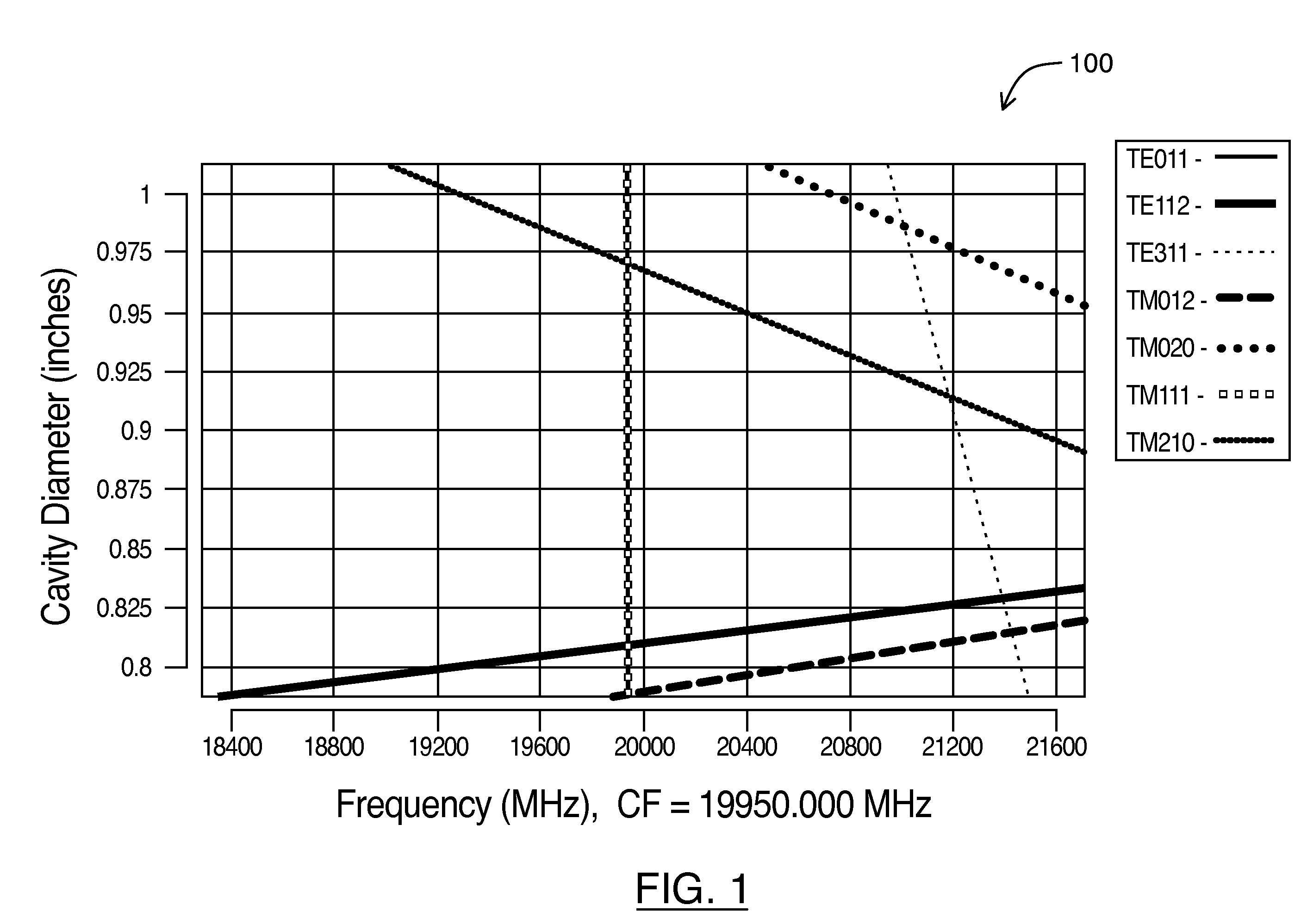
Microwave TE011 single mode cavity filters have been around for many years. TE011 mode operation offers a very high quality factor that makes them attractive for a number of applications, including low loss and high power filters. Additionally, a TE011 mode cavity resonator is frequently used for its clean...


PUM


Abstract

A TE011 cavity filter assembly is disclosed. The system includes at least one resonator operating in TE011 mode having a resonant frequency. The at least one resonator may include a cavity comprising an inner diameter and a cavity length. The at least one resonator may also include a first metal disc inside the cavity. The first metal disc may include a disc diameter and a void in the metal disc, which includes a void diameter and a void depth. The inner diameter of the cavity may be greater than the disc diameter creating a gap with a gap width and a gap depth. The TE011 cavity filter assembly may further include positive coupling.

Description

FIELDEmbodiments described herein relate to assemblies and methods for creating a TE011 cavity filter assembly. More particularly, embodiments described herein relate to systems for creating a TE011 cavity filter assembly including a metal disc inside the cavity filter assembly and positive and negative coupling.BACKGROUNDA microwave filter is an electromagnetic circuit that can be tuned to pass energy at a specified resonant frequency. Accordingly, microwave filters are commonly used in telecommunication applications to transmit energy in a desired band of frequencies (i.e. the passband) and reject energy at unwanted frequencies (i.e. the stopband) that are outside the desired band. In addition, the microwave filter should preferably meet some performance criteria for properties, which typically include insertion loss (i.e. the minimum loss in the passband), loss variation (i.e. the flatness of the insertion loss in the passband), rejection or isolation (the attenuation in the stop...

Claims


Application Information

Patent Timeline
IPC IPC(8): H01P1/207
CPCH01P1/208H01P7/06
Inventor YASSINI, BAHRAMYU, MING
Owner COM DEV LTD
Why Eureka
Try Eureka