[0009]In view of the problems and inconveniences inherent in the mercury measurement hitherto encountered with, the present invention has for its object to provide a mercury measuring apparatus of a
closed system, in which a process
ranging from collection to injection of the sample composed mainly of hydrocarbon is performed automatically, which is effective to provide stable data of a high reliability, and which is easy to operate and capable to measuring the mercury in a short in a matter of minutes.
[0012]With the mercury measuring apparatus according to the present invention, since the apparatus automatically performs a process
ranging from collection to measurement of the sample composed mainly of hydrocarbon, there is no need for the operator to insert the column, in which mercury has been adsorbed, into the mercury measuring unit such as required in the prior art disclosed in the
Patent Document 1 above. Also, since the apparatus is designed of the
closed system, stable data having a high reliability can be obtained and the apparatus can be easily operated to accomplish the intended measurement in a matter of minutes.
[0014]In the mercury measuring apparatus of the present invention, the
control unit is preferably of a type capable of executing the
metal mercury isolating step and the measuring step simultaneously. Particularly where the content of mercury contained in the sample is high, simultaneous execution of the
metal mercury isolating step and the measuring step is effective to lower the measuring sensitivity and, therefore, the sample can be measured with no need to dilute the sample.
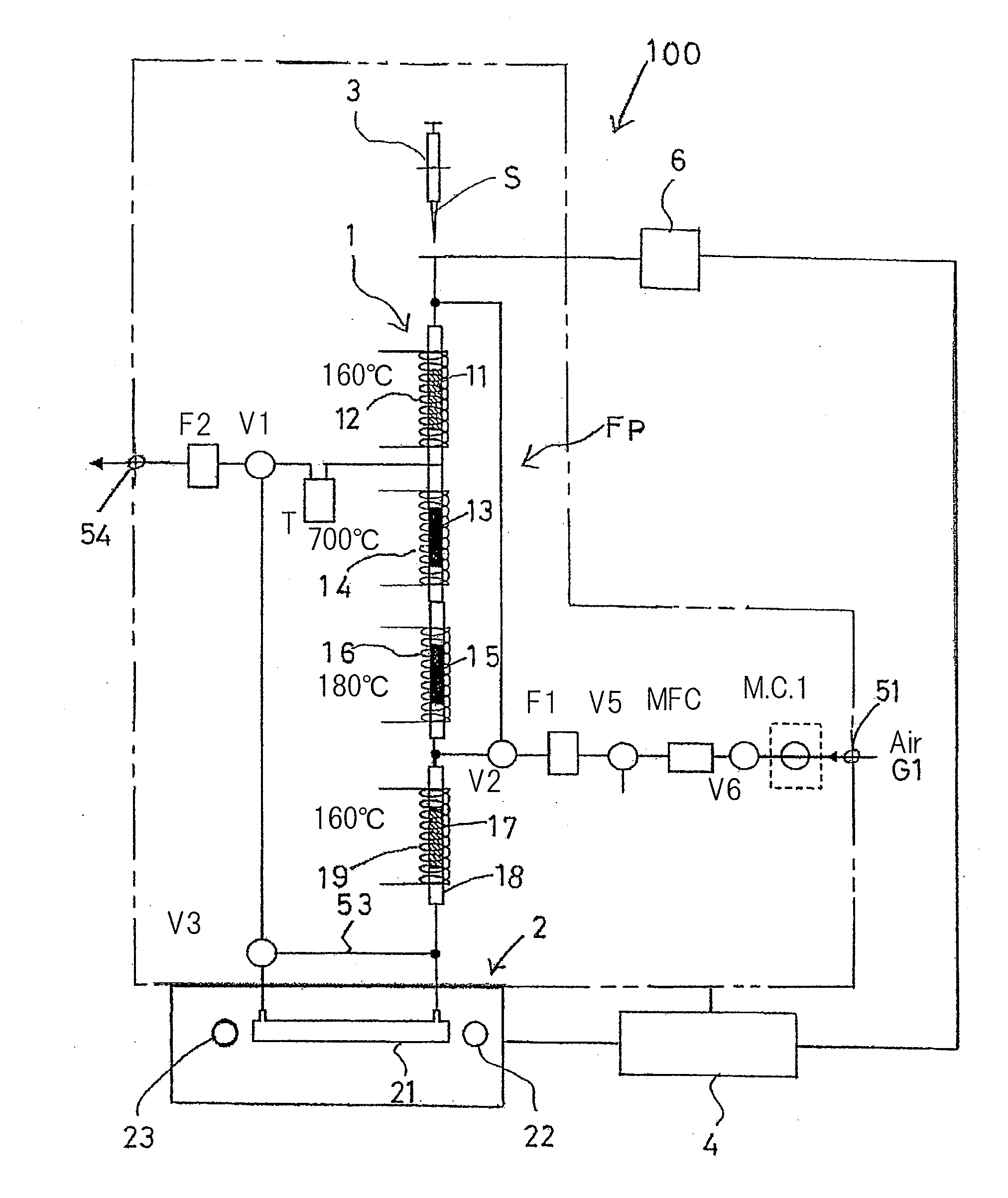
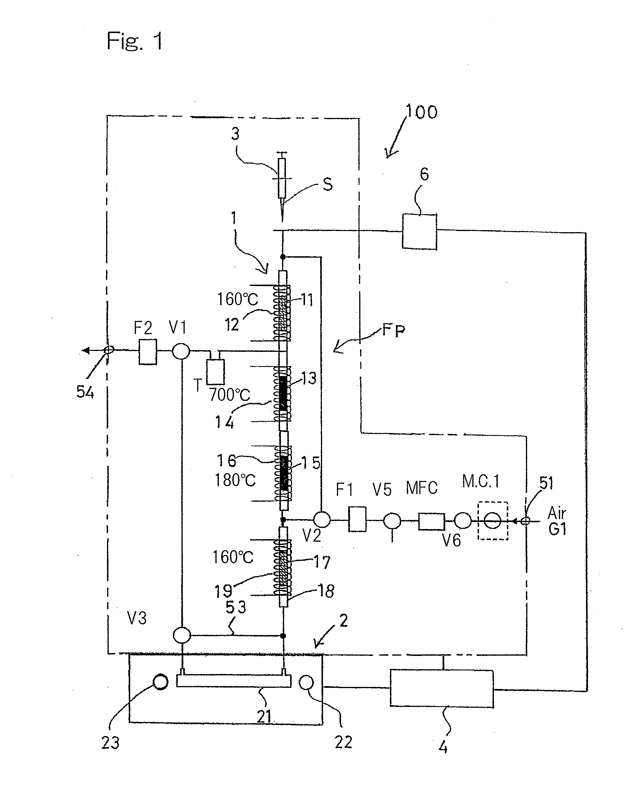
[0015]In the mercury measuring apparatus of the present invention, the gas flow path preferably includes a first gas introducing port, through which a first carrier gas is introduced, and a second gas introducing port, through which a second carrier gas is introduced, in which case the mercury measuring unit is preferably employed in the form of a mercury
atomic fluorescence spectrophotometer. The provision of the first gas introducing port and the second gas introducing port makes it possible for two kinds of gases to be introduced and, therefore, the measurement with high sensitivity can be accomplished with the mercury
atomic fluorescence spectrophotometer, which forms the mercury measuring unit employed in the practice of the present invention.
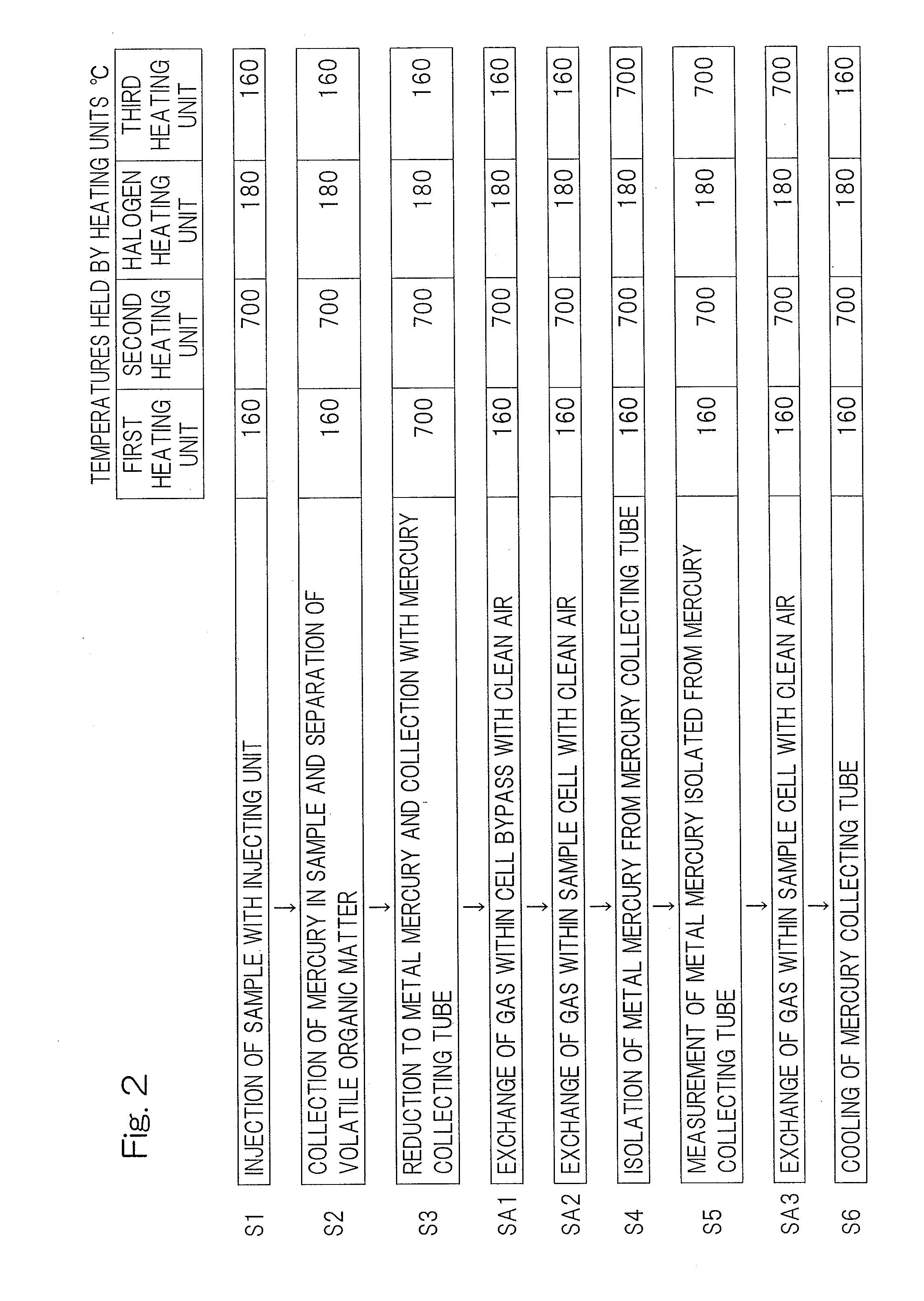
[0016]In such case, the first carrier gas is preferably introduced from the first gas introducing port during the sample injecting step, the collecting and separating step and the mercury reducing and collecting step, but the second carrier gas is preferably introduced from the second gas introducing port during the
metal mercury isolating step and the measuring step, and the mercury measuring unit is preferably employed in the form of a mercury atomic
fluorescence spectrophotometer. When the first gas suitable for sample injection, collection and separation, and also mercury reduction and collection is introduced, mercury and a volatile
organic matter, both contained in the hydrocarbon, can be assuredly separated from each other with the mercury collected by the adsorbent and, on the other hand, when the second gas suitable for
metal mercury isolation and measurement is introduced, it can be measured by the mercury atomic
fluorescence spectrophotometer, which forms the mercury measuring unit, with a high sensitivity.
[0017]The mercury measuring apparatus of the present invention may preferably include a sample exchanger for exchanging a plurality of samples, which exchanger is controlled by the
control unit. This is particularly advantageous that the plurality of the samples can be automatically measured continuously.
