Pyroelectric temperature sensor and a method for measuring a temperature with the pyroelectric temperature sensor

a temperature sensor and pyroelectric technology, applied in the direction of instruments, heat measurement, measurement devices, etc., can solve the problems of complex external circuits, inability to obtain an amplification characteristic greater than that of thin film transistors, and inability to detect the amount of drain current, etc., to achieve high sensitivity

Active Publication Date: 2011-12-08
PANASONIC CORP
View PDF17 Cites 17 Cited by
  • Summary
  • Abstract
  • Description
  • Claims
  • Application Information

AI Technical Summary

Benefits of technology

[0035]The present subject matter provides a method for measuring a temperature using a pyroelectric temperature sensor with high sensitivity.
[0036]Other features, elements, processes, steps, characteri

Problems solved by technology

However, according to the patent document 1, it is impossible to obtain an amplification characteristic greater than that of

Method used


Image

  • Pyroelectric temperature sensor and a method for measuring a temperature with the pyroelectric temperature sensor
  • Pyroelectric temperature sensor and a method for measuring a temperature with the pyroelectric temperature sensor
  • Pyroelectric temperature sensor and a method for measuring a temperature with the pyroelectric temperature sensor

Examples


embodiment 1

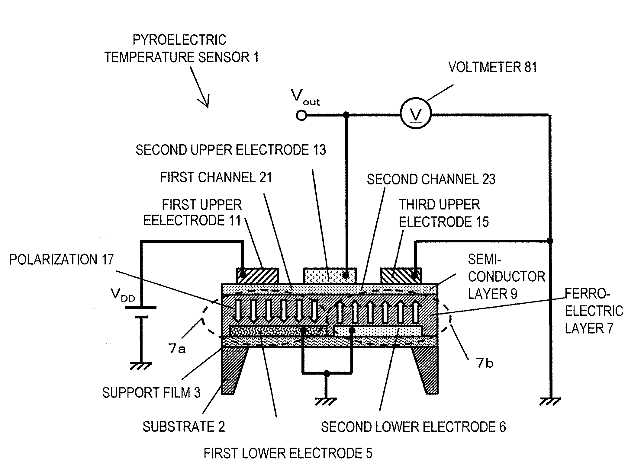
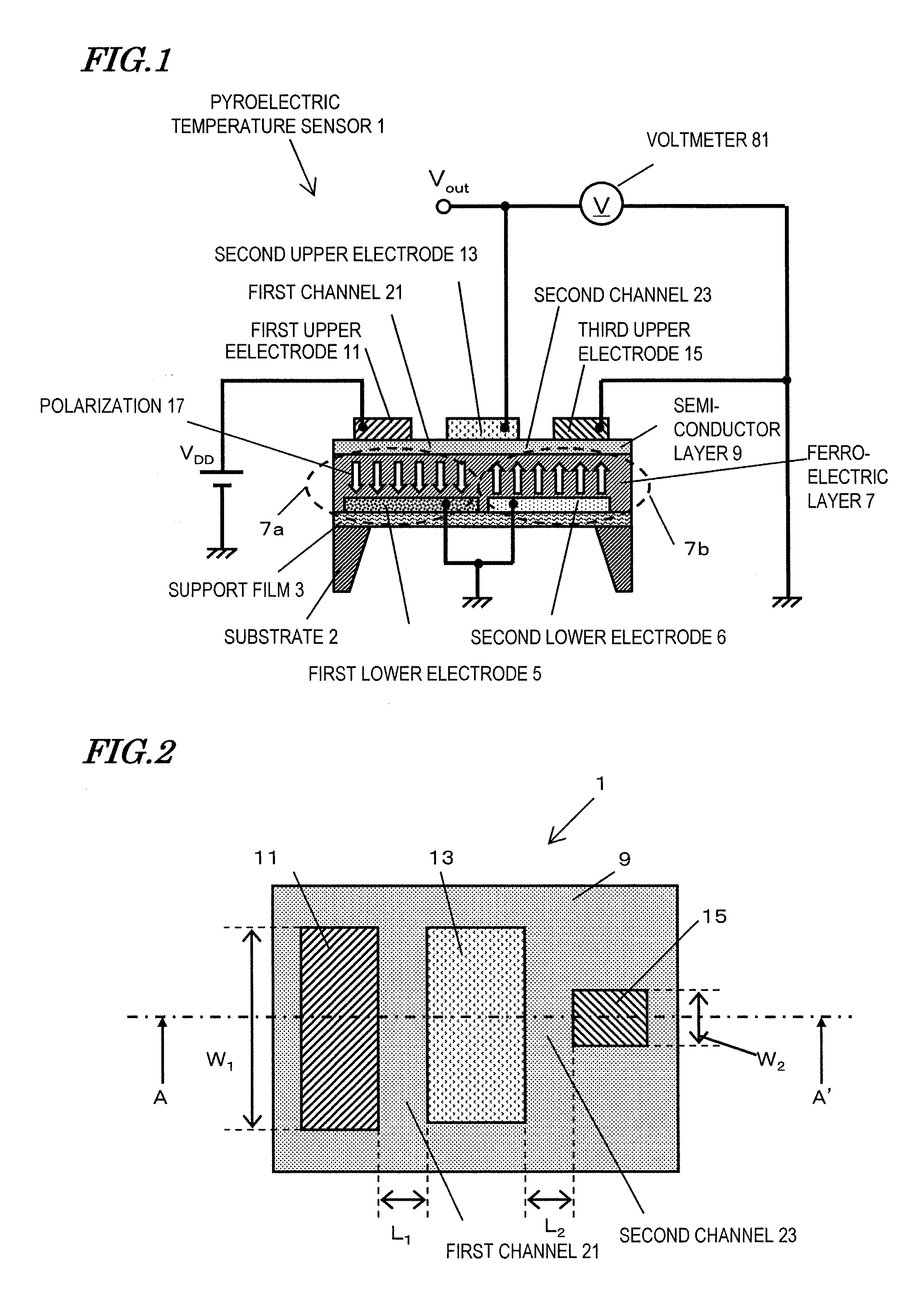
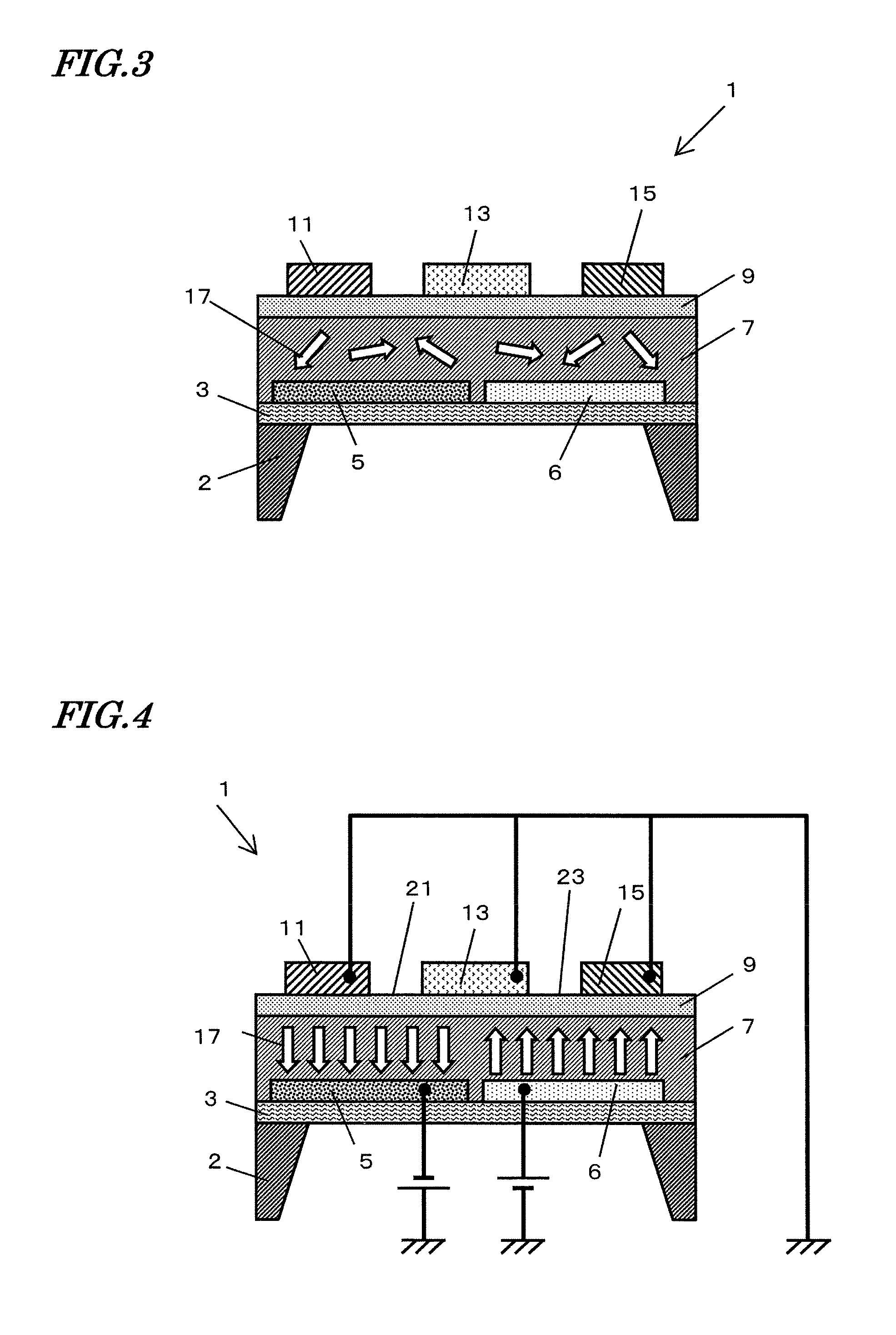
[0053]FIG. 1 shows the pyroelectric temperature sensor 1 according to the embodiment 1.

[0054]As shown in FIG. 1, the present pyroelectric temperature sensor 1 comprises a substrate 2, a support film 3, a lower electrode group 5, 6, a ferroelectric layer 7 as a pyroelectric layer, a semiconductor layer 9, and an upper electrode group 11, 13, 15.

[0055]The lower electrode group 5, 6, the ferroelectric layer 7, the semiconductor layer 9, and the upper electrode group are stacked in this order.

[0056]The lower electrode group comprises a first lower electrode 5 and a second lower electrode 6.

[0057]The upper electrode group comprises a first upper electrode 11, a second upper electrode 13, and a third upper electrode 15.

[0058]The second upper electrode 13 is interposed between the first upper electrode 11 and the third upper electrode 15 in a plan view.

[0059]A first channel 21 is formed in the portion of the semiconductor 9 which is interposed between the first upper electrode 11 and the s...

example 1

[0091]FIG. 6 shows a method of fabricating a pyroelectric temperature sensor.

[0092](a) A SrTiO3 film with a thickness of 150 nm was deposited on a MgO(100) monocrystalline substrate 2 under a temperature of 700 degree Celsius with a pulse laser deposition method (hereinafter “PLD process”) to form a support film 3.

[0093]After the temperature of the substrate 2 was set to be 400 degree Celsius, a platinum film with a thickness of 200 nm was deposited with the PLD process. A resist (not shown) was applied and patterned to form an etching mask. The platinum film was etched with reactive ion etching process using CF4 gas. Subsequently, as shown in FIG. 6A, the first lower electrode 5 and the second lower electrode 6 were formed.

[0094](b) After the temperature of the substrate 2 was set to be 600 degree Celsius, a PLT film of a thickness of 500 nm was deposited with the PLD process. Thus, as shown in FIG. 6B, the ferroelectric layer 7 was deposited. The ratio of Pb to La in the(Pb,La)TiO...

example 2

[0103]FIG. 9 shows a graph in which the horizontal axis represents the channel size ratio α, and the vertical axis represents the output voltage change. The output change is defined as the output voltage change of the pyroelectric temperature sensor when the temperature increased from 20 degree Celsius to 80 degree Celsius. As shown in FIG. 9, when the polarization direction of the first ferroelectric part is substantially downward from the semiconductor layer to the lower electrode group, the output voltage change becomes greater in accordance with the increase of α. Since the lower detection limit of the voltage change was 0.1 mV, detectable output voltage change is obtained when the value of α is not less than 30. Preferably, the value of α is not less than 300 since the output voltage change of not less than 1 mV is obtained.


PUM


Abstract

A temperature sensor includes first and second lower electrodes, a ferroelectric layer having polarization, a semiconductor layer; and first to third upper electrodes. The second upper electrode is interposed between the first upper electrode and the third upper electrode in a plan view. The semiconductor layer includes a first channel disposed between the first upper electrode and the second upper electrode, and a second channel disposed between the second upper electrode and the third upper electrode. The ferroelectric layer includes a first ferroelectric part disposed below the first channel and a second ferroelectric part disposed below the second channel. A polarization direction of the first ferroelectric part is opposite to a polarization direction of the second first ferroelectric part. The temperature is calculated based on the output voltage from the second upper electrode and the voltage applied to the first upper electrode.

Description

[0001]This is a continuation of International Application No. PCT / JP2011 / 000888, with an international filing date of Feb. 17, 2011, which claims priority of Japanese Patent Application No. 2010-053977, filed on Mar. 11, 2010, the contents of which are hereby incorporated by reference.BACKGROUND OF THE INVENTION[0002]1. Field of the Invention[0003]The present disclosure relates to a pyroelectric temperature sensor and a method for measuring the temperature with a pyroelectric temperature sensor.[0004]2. Description of the Related Art[0005]An amount of charge on the surface of a pyroelectric body increases or decreases depending on temperature change. This is referred to as pyroelectric effect. A pyroelectric temperature sensor detects temperature by utilizing the pyroelectric effect. Japanese Laid-open patent publication No. Hei 2-137268 (Hereinafter, Patent document 1) discloses a conventional pyroelectric temperature sensor comprising a structure of a pyroelectric body and a semic...

Claims


Application Information

Patent Timeline
IPC IPC(8): G01K7/36
CPCH01L37/02G01K7/36H10N15/10
Inventor UEDA, MICHIHITOTANAKA, HIROYUKIKANEKO, YUKIHIROFUJII, EIJI
Owner PANASONIC CORP
Why Eureka
Try Eureka