Sensor calibration in an RFID tag

a technology of sensor calibration and rfid tag, which is applied in the direction of instruments, heat measurement, liquid/fluent solid measurement, etc., can solve the problems of time-consuming and special equipment for calibration processes, insignificant absolute accuracy, and related costs, and achieve the effect of reducing or even eliminating these calibration costs

Inactive Publication Date: 2011-12-08
NXP BV
View PDF3 Cites 47 Cited by
  • Summary
  • Abstract
  • Description
  • Claims
  • Application Information

AI Technical Summary

Benefits of technology

[0010]A calibration procedure typically includes checking, adjusting or determining a numerical value by comparison with a standard or another reference. As is known in the art, calibration processes are time-consuming and require special equipment. Related...

Problems solved by technology

As is known in the art, calibration processes are time-consuming and require special equipment.
Related costs are usually commercially not relevant for high-precision sensors, but they are a major factor for ultra-low cost applications such as RFID tags used in, e.g., supply chain monit...

Method used


Image

  • Sensor calibration in an RFID tag
  • Sensor calibration in an RFID tag
  • Sensor calibration in an RFID tag

Examples


Embodiment Construction

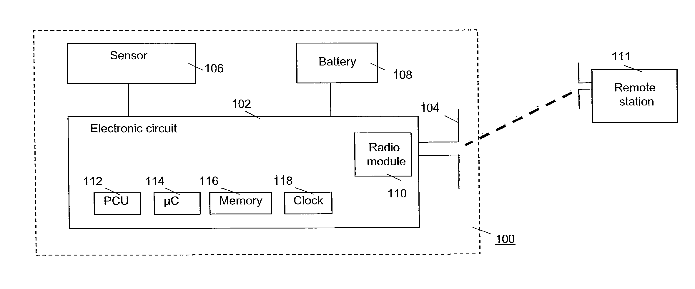
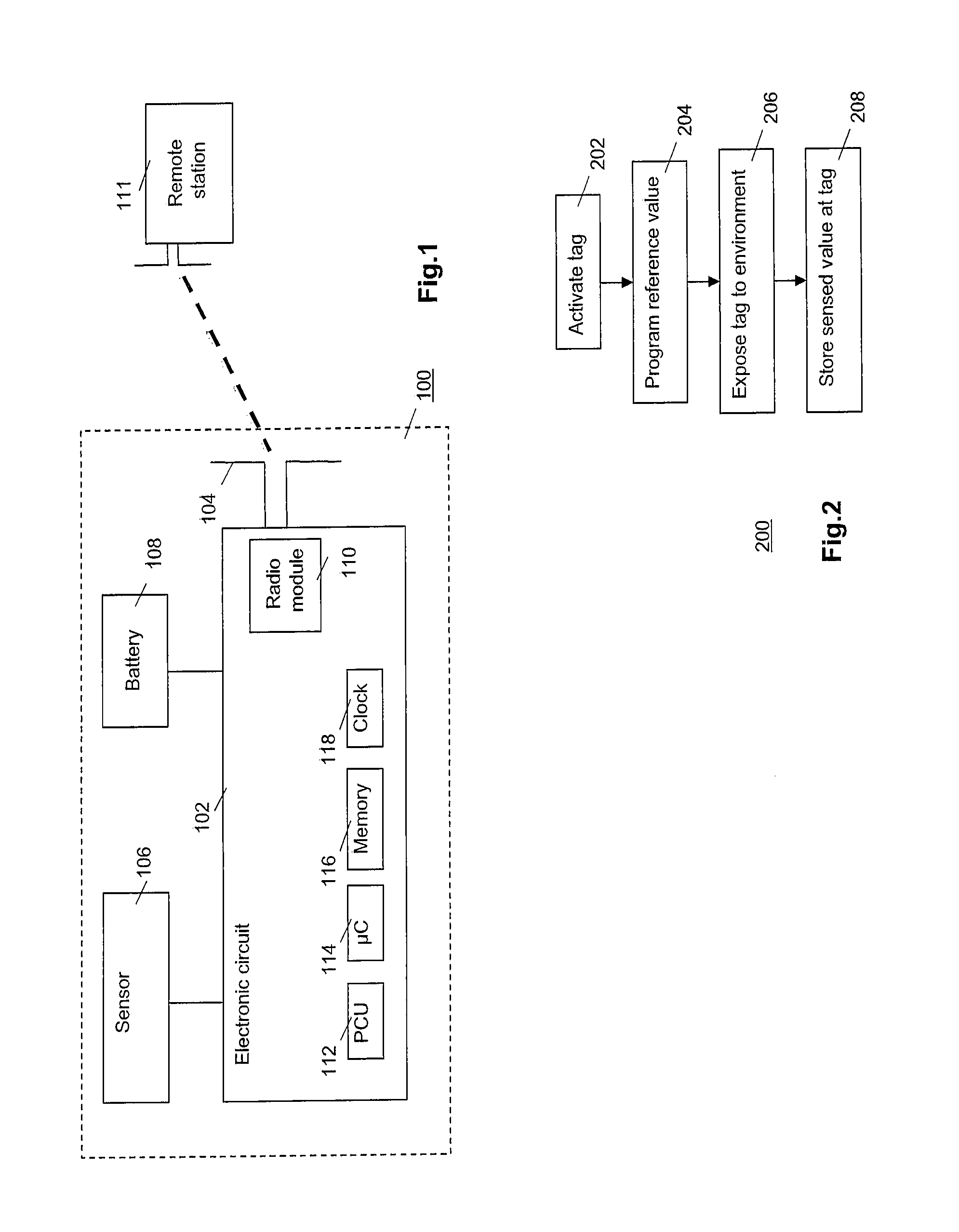
[0029]FIG. 1 is a diagram of the main components of a transponder device 100, for example, an active RFID tag. Tag 100 comprises an electronic circuit 102, and antenna 104, a sensor 106 and a power supply 108 such as a battery. Tag 100 is drawn as composed of separate components for clarity. It is understood that the components may be physically integrated with one another, e.g., sensor 106 and / or battery 108 may also be physically integrated with electronic circuit 102 into the same die. Circuit 102 includes a radio module 110 for sending data to, and / or receiving data from, a remote reading / programming station 111, a power control unit (PCU) 112, a microprocessor or microcontroller 114, a memory 116 and an optional clock 118, e.g., an LC-circuit or a quartz crystal oscillator. Preferably, station 111 communicates with device 100 using a wireless connection, e.g., using a radio-frequency communication technology. The configuration and operation of tag 100 is well known in the art a...


PUM


Abstract

A sensor, electrically connected to transponder, is calibrated in an environment of operational use of the transponder. The calibrating uses as a reference a value of a parameter representative of the environment.

Description

FIELD OF THE INVENTION[0001]The invention relates to a method of calibrating a sensor electrically connected to a transponder.BACKGROUND ART[0002]Over 600 million RFID (radio frequency identification) tags were delivered in 2005. Applications of such tags range from identification and access control to counterfeit prevention and logistics. Supply chain monitoring is a huge market for active tags equipped with sensor and memory to store the measured data. For example, tags with a temperature sensor constantly record the actual temperature of frozen food or goods that need to be cooled. Depending on the “thermal budget”, i.e. the temperature integrated over time during storage and transport, the shelf-life of the product is calculated on an individual basis. Moreover, the tags can indicate if certain limits, e.g. maximum or minimum temperature, have been exceeded and if the product must be discarded. Besides temperature, there are numerous other variables such as pH and gas compositio...

Claims


Application Information

Patent Timeline
IPC IPC(8): G01D18/00
CPCG01D18/008G01K15/00G01K3/04G01K1/024
Inventor HUMBERT, ARELIECURATOLA, GILBERTMERZ, MATTHIASPIJENBURG, REMCO HENRICUS WILHELMUSHOOFMAN, ROMANOPONOMAREV, YOURI
Owner NXP BV
Why Eureka
Try Eureka