
Hydrogen storage method and system

a technology of hydrogen storage and hydrogen sulfide, applied in hydrogen sulfides, transportation and packaging, separation processes, etc., can solve the problems of carbon dioxide contamination, extremely low carbon dioxide contamination level, and extremely slow hydrogen transport process

Active Publication Date: 2011-12-15
PRAXAIR TECH INC
View PDF4 Cites 45 Cited by
  • Summary
  • Abstract
  • Description
  • Claims
  • Application Information

AI Technical Summary

Benefits of technology

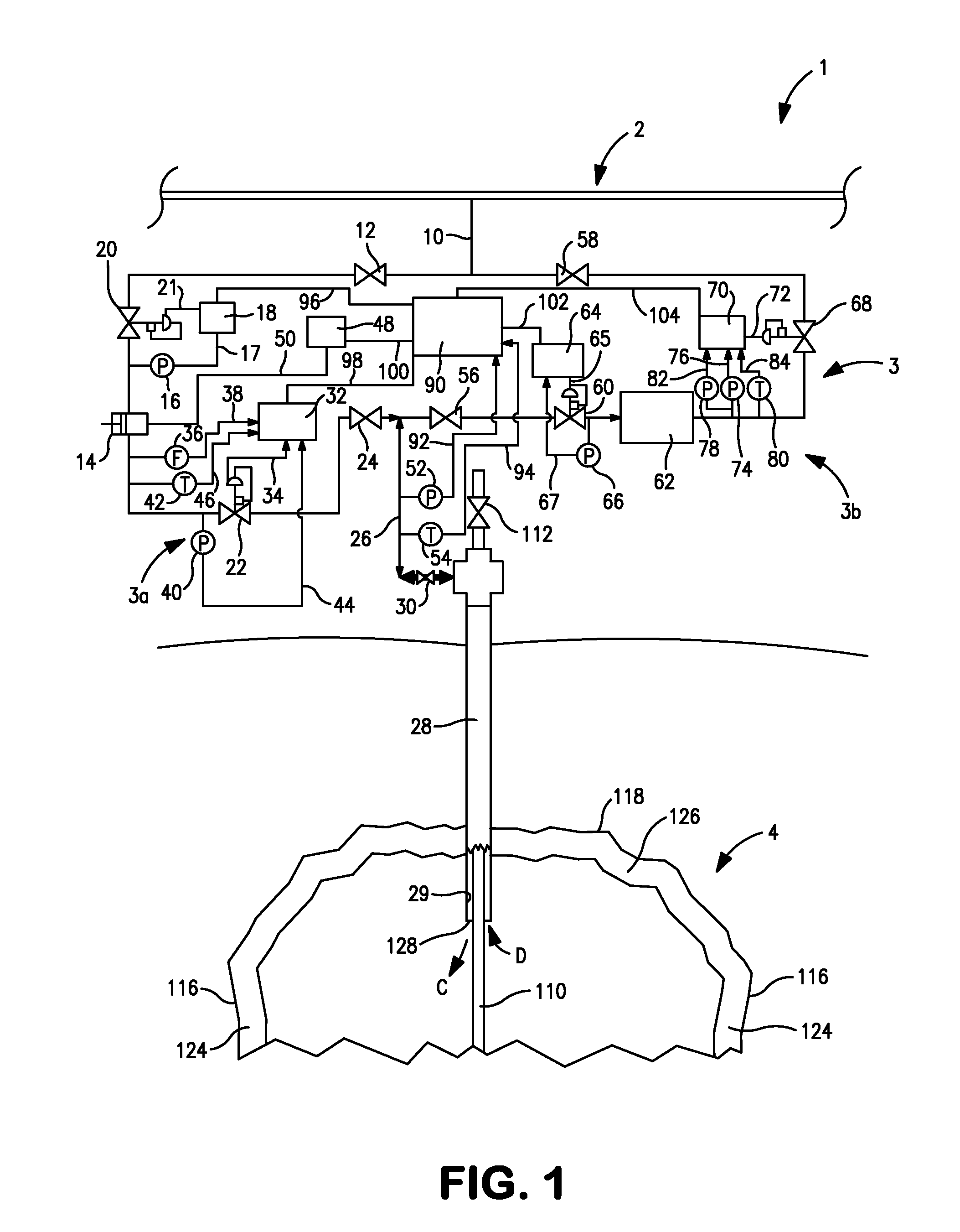
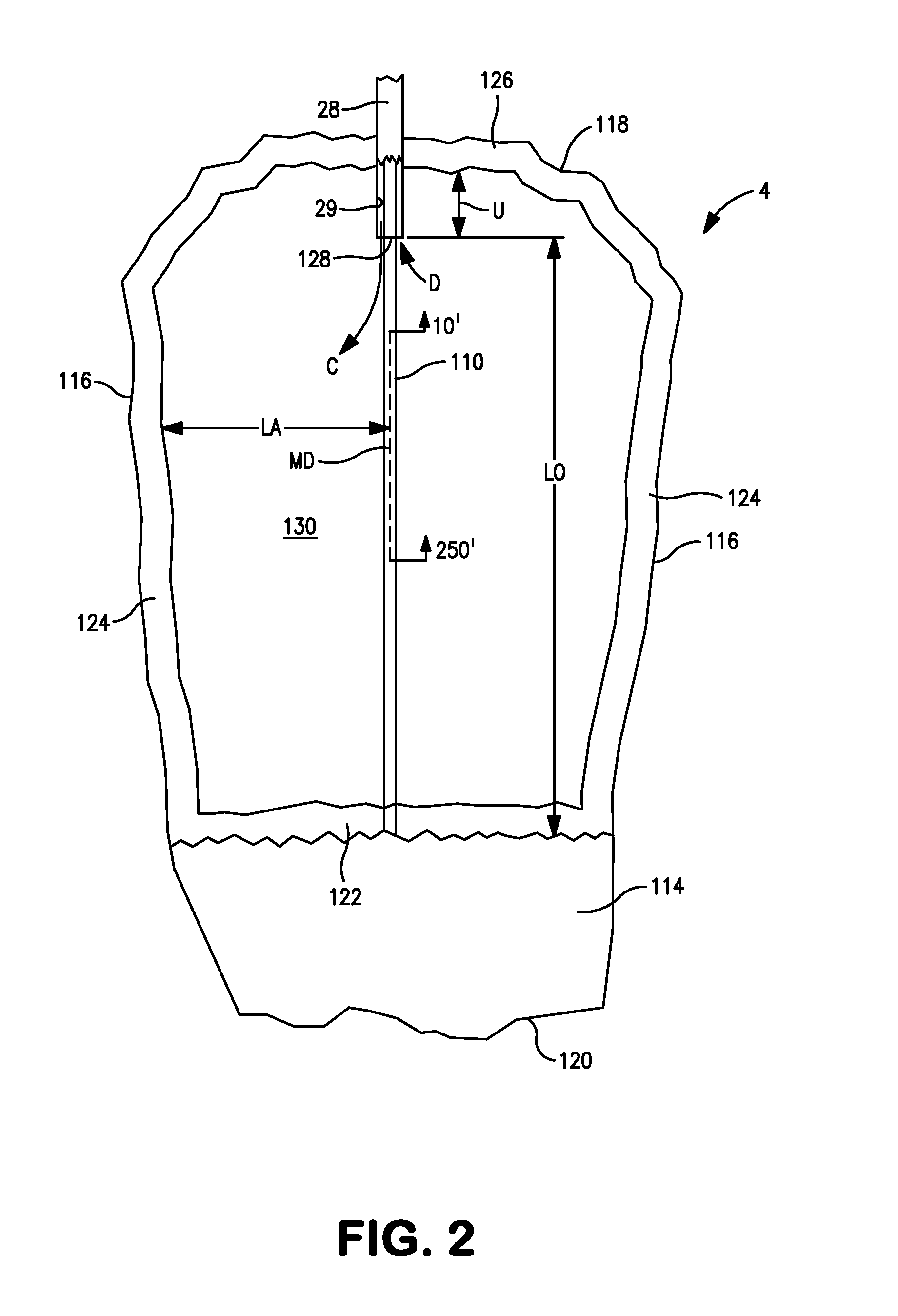
Furthermore, in either aspect of the present invention, the minimum volume of the hydrogen stored within the salt cavern can be maintained at a volume ratio equal to a stored volume of the hydrogen to the actual cavern volume of no less than 29.0 scf / cf. It is to be noted here that, as used herein and in the claims, the unit “scf / cf” means standard cubic feet of the stored hydrogen per actual cubic feet of the cavern volume able to contain the stored hydrogen. The actual cubic feet of cavern volume able to contain the stored hydrogen is computed by subtracting the volume of the residual brine layer from the total volume of the salt cavern. In case the at least one lower end of the at least one conduit is open, rather than incorporating a flow diffuser, the at least one lower end of the at least one conduit can be spaced from the residual brine layer at a lower vertical distance of no less than 250 feet and is also spaced from the side regions of the salt cavern at a lateral distance of no less than 40 feet as measured from a vertical line extending between 10 and 250 feet below the at least one lower end of the at least one conduit. The flow rates and velocities are limited such that, as measured at the at least one lower end of the at least one conduit, the compressed hydrogen feed stream is injected at an injection ratio equal to an injection flow rate of the compressed hydrogen feed stream to the actual cavern volume of no greater than 7.5 scfd / cf and at an injection velocity of the compressed hydrogen feed stream of no greater than 100 feet per second and the stored hydrogen stream is withdrawn at a withdrawal ratio equal to the withdrawal flow rate of the stored hydrogen stream to the actual cavern volume of no greater than 10.0 scfd / cf and at a withdrawal velocity of the stored hydrogen stream of no greater than 150 feet per second. It is to be mentioned that, as used herein and in the claims, the unit “scfd / cf” means the flow rate measured in standard cubic feet per day per cubic feet of the actual cavern volume that is able to store the stored hydrogen.
Where the at least one lower end of the at least one conduit is spaced below a top region of the salt cavern, the at least one lower end can be spaced from the top region of the salt cavern at an upper vertical distance of no less than 50 feet.
In the aspect of the present invention relating to the method, where the hydrogen feed stream contains less than 1.0 ppmv carbon dioxide and less than 8 ppmv carbon monoxide, a sum of a carbon dioxide content and carbon monoxide content in the stored hydrogen stream is to be less than 10 ppmv. Where hydrogen feed stream contains less than 0.1 ppmv carbon dioxide and less than 0.6 ppmv carbon monoxide, a sum of a carbon dioxide content and carbon monoxide content in the stored hydrogen stream is less than 1.0 ppmv. The unit “ppmv” as used herein and in the claims means parts per million by volume on a dry basis or in other words without considering the water content.

Problems solved by technology

The stagnant layer has a carbon dioxide content that is a potential source of carbon dioxide contamination to the stored hydrogen stream.
However, any such carbon dioxide contamination is at an extremely low level given that it will arise from molecular diffusion of the hydrogen from the stagnant layer to the interior region and such transport of hydrogen is an extremely slow process.

Method used


Image

  • Hydrogen storage method and system
  • Hydrogen storage method and system
  • Hydrogen storage method and system

Examples


Embodiment Construction

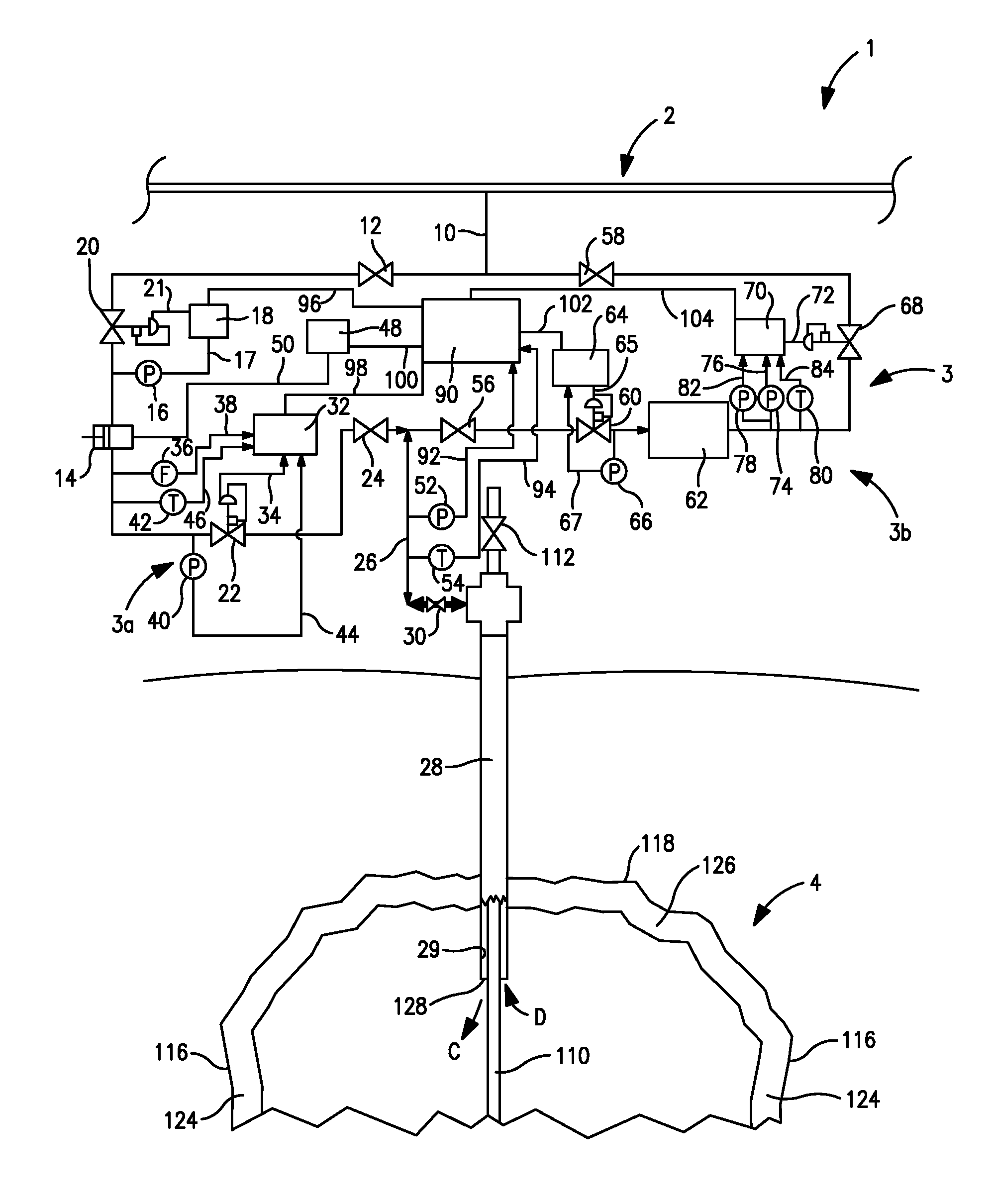
With reference to FIG. 1 a system 1 is illustrated for storing and supplying hydrogen to a hydrogen pipeline 2. Hydrogen traverses the hydrogen pipeline 2 in a direction taken from point “A” to point “B”, from a facility used in generating the hydrogen to customers consuming the hydrogen. The hydrogen generation facility can employ a steam methane reformer to reform a hydrocarbon containing stream into a hydrogen and carbon monoxide containing stream. Such facility typically also uses one or more stages of water-gas shift to react the carbon monoxide with steam and generate additional hydrogen and a hydrogen pressure swing adsorption unit to purify the resulting shifted stream and thereby generate the hydrogen product.

Briefly, the present invention contemplates drawing off a hydrogen feed stream from the hydrogen pipeline 2 during periods of low customer demand and then compressing the hydrogen within a compression side 3a of a flow network 3 to produce a compressed hydrogen feed st...


PUM


Abstract

A method and system for storing and supplying hydrogen to a hydrogen pipeline in which a compressed hydrogen feed stream is introduced into a salt cavern for storage and a stored hydrogen stream is retrieved from the salt cavern and reintroduced into the hydrogen pipeline. A minimum quantity of stored hydrogen is maintained in the salt cavern to produce a stagnant layer having a carbon dioxide content along the cavern wall and the top of a residual brine layer located within the salt cavern. The compressed hydrogen feed stream is introduced into the salt cavern and the stored hydrogen stream is withdrawn without disturbing the stagnant layer to prevent carbon dioxide contamination from being drawn into the stored hydrogen stream being reintroduced into the hydrogen pipeline. This allows the stored hydrogen stream to be reintroduced into the hydrogen pipeline without carbon dioxide removal.

Description

FIELD OF THE INVENTIONThe present invention relates to a hydrogen storage method and system in which hydrogen is stored in a salt cavern and introduced from the salt cavern into a hydrogen pipeline without removal of carbon dioxide.BACKGROUND OF THE INVENTIONHydrogen is utilized in a variety of industrial processes and is typically produced from the steam methane reforming of hydrocarbons that are contained in natural gas. The hydrogen after production can be used on site where the steam methane reformer is located or can be distributed to customers with the use of a pipeline.Customer demand will typically vary and it has been found to be advantageous to store the hydrogen when customer demand is low for later use during peak demand periods. One central advantage in storing the hydrogen is that the hydrogen production facility does not have to be sized to meet peak customer demands and thus, can be a smaller, lower cost installation. Additionally, the storage of hydrogen also allows...

Claims


Application Information

Patent Timeline
Patent Type & Authority Applications(United States)
IPC IPC(8): B65G5/00F17D1/07
CPCB65G5/00Y02E60/322C01B3/34C01B3/48C01B2203/0233C01B2203/0283C01B2203/0288C01B2203/0294C01B2203/043F17C1/007F17C2221/012F17C2265/068F17C2270/0152Y02C10/14F17C2221/013F17C2223/0123F17C2223/036Y02E60/324Y02E60/321C01B3/00Y02E60/32Y02C20/40B01D53/261B01D53/263
Inventor DRNEVICH, RAYMOND FRANCIS
Owner PRAXAIR TECH INC
Learn More