Material removal device and method of use

a technology of material removal and a method, applied in the field of catheters, can solve the problems of skin ulceration, low blood flow, and pain in the legs, and achieve the effects of improving blood circulation, improving blood circulation, and improving blood circulation

Active Publication Date: 2011-12-15
TYCO HEALTHCARE GRP LP
View PDF11 Cites 103 Cited by
  • Summary
  • Abstract
  • Description
  • Claims
  • Application Information

AI Technical Summary

Benefits of technology

[0015]This embodiment of the invention as well as the other embodiments disclosed herein may further comprise means to direct material removed from the vascular lum...

Problems solved by technology

Over time atheromatous deposits can become large enough to reduce or occlude blood flow through the vessels, leading to symptoms of low blood flow, such as pain in the legs (on walking or at rest), skin ulcer, angina (at rest or exertional), and other symptoms.
All have challenges, however, such as traversing through small and tortuous arteries to get to the plaque occluded target zone or zones.
This can be especially difficult if the treatment site has been totally occluded by the plaque.
Another challenge lies in the inability to safely and efficiently handle and remove the plaque which is removed from the vessel walls during the atherectomy procedure.
Some devices are not designed to handle the liberated plaque fragments at all and instead let the fragments migrate through the circulation.
This can cause many problems because the liberated plaque remnants can be thrombogenic and can end up causing downstream occlusions.
Although the SilverHawk® catheter represents a significant advance over prior art devices challenges remain for atherectomy catheters.
For example, if the treatment site is a CTO (chronic total occlusion) it might not be possible to cross the lesion with the catheter.
If the CTO can not be crossed with the atherectomy catheter to enable it to be placed in a proper treatment...

Method used


Image

  • Material removal device and method of use
  • Material removal device and method of use
  • Material removal device and method of use

Examples


Embodiment Construction

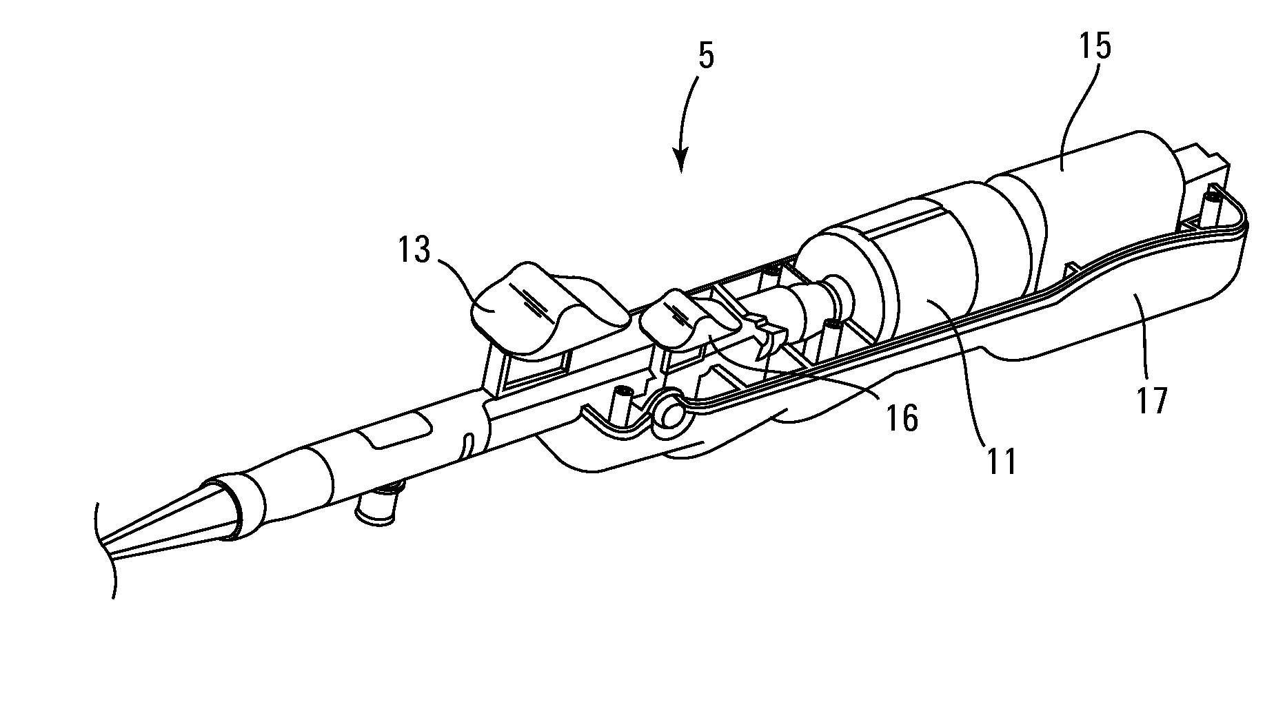
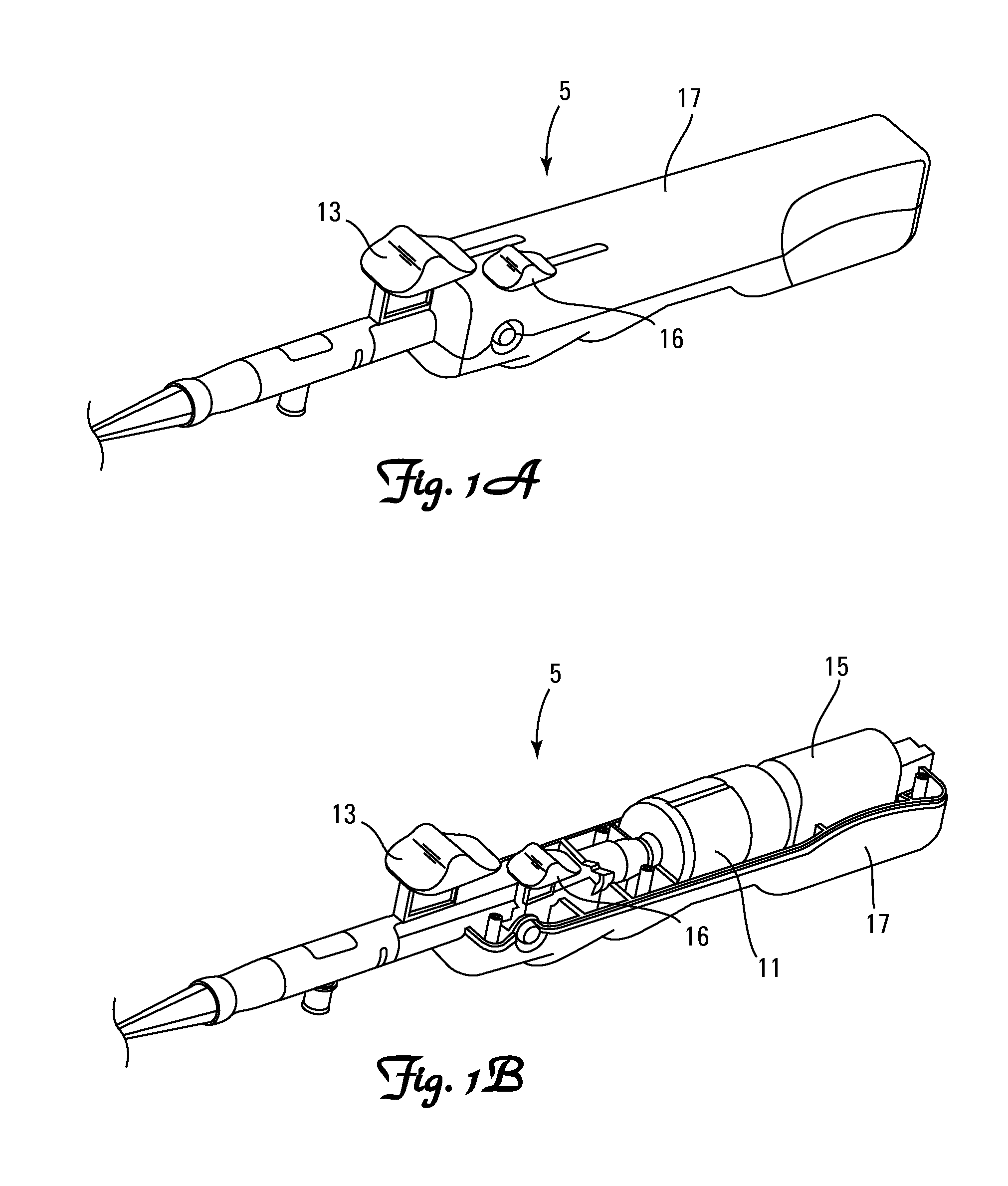
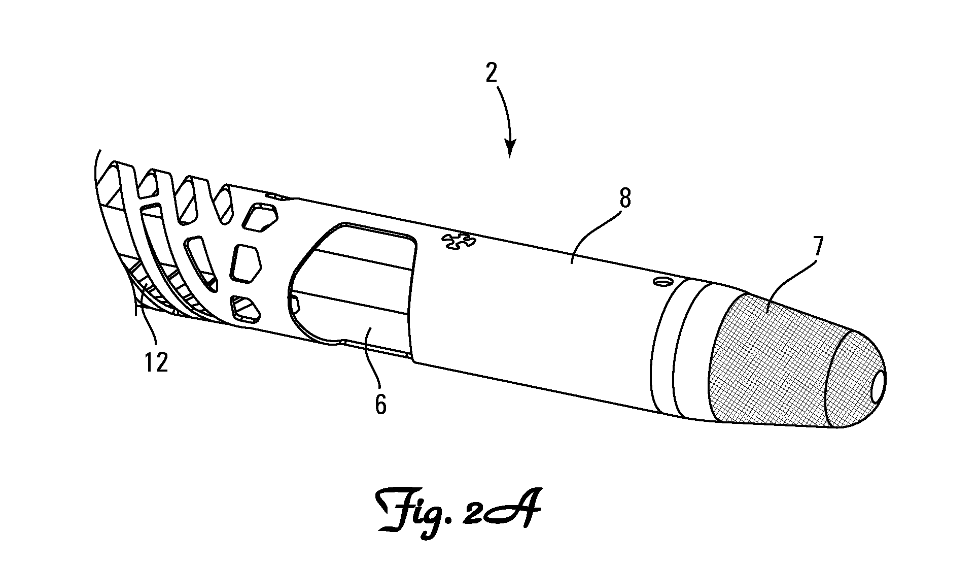
[0041]Apparatus according to the present invention will generally comprise catheters having catheter bodies adapted for intraluminal introduction to the target body lumen. The dimensions and other physical characteristics of the catheter bodies will vary significantly depending on the body lumen which is to be accessed. In the exemplary case of atherectomy catheters intended for intravascular introduction, the distal portions of the catheter bodies will typically be very flexible and suitable for introduction over a guidewire to a target site within the vasculature. In particular, catheters can be intended for “over-the-wire” introduction when a guidewire channel extends fully through the catheter body or for “rapid exchange” introduction where the guidewire channel extends only through a distal portion of the catheter body. In other cases, it may be possible to provide a fixed or integral coil tip or guidewire tip on the distal portion of the catheter or even dispense with the guid...


PUM


Abstract

A catheter having a tubular body and a rotatable shaft disposed within a lumen of the tubular body. A cutting element is coupled to the rotatable shaft, the cutting element having a cutting edge, the cutting element and rotatable shaft being longitudinally moveable within the tubular body between a stored position in which the cutting element is positioned distal of a side opening and a cutting position in which the cutting element is contained within the lumen of the tubular body and longitudinally aligned with the side opening. The cutting element is configured to extend through the side opening and to cut material from the wall of a vessel at a treatment site as the catheter is pulled proximally through the treatment site. The catheter may optionally have a rotating distal tip with an abrasive surface. The catheter includes a collection chamber positioned proximally of the cutting window.

Description

[0001]This application claims the benefit of U.S. Provisional Patent Application No. 61 / 354,487, filed Jun. 14, 2010, entitled “Material Removal Device and Method of Use”, the contents of which are hereby incorporated by reference herein.FIELD OF THE INVENTION[0002]The present invention relates to catheters used to remove and collect material from a treatment site in a body lumen. More particularly, this invention pertains to catheters capable of crossing a totally occluded treatment site in a vessel to enable the catheter to effectively treat the vessel at the treatment site.BACKGROUND OF THE INVENTION[0003]Atherosclerosis is a progressive disease of the vascular system whereby atheroma is deposited on the inner walls of blood vessels. Atherosclerosis is a complex, progressive and degenerative condition resulting in the build-up of cholesterol and other obstructive materials, known as plaque, on the walls of the arteries. The accumulation of plaque narrows the interior or lumen of ...

Claims


Application Information

Patent Timeline
IPC IPC(8): A61B17/22
CPCA61B2017/320791A61B17/320783A61B17/22A61B17/3207A61B17/34A61M25/01A61B17/320758
Inventor MOBERG, JOHN ROBERT
Owner TYCO HEALTHCARE GRP LP
Why Eureka
Try Eureka