On the night of Apr. 20, 2010, a catastrophic and deadly explosion occurred at the Deepwater
Horizon oil well in the Gulf of Mexico, breaking the well's riser pipe, and causing what would become the
petroleum industry's largest accidental release of oil into the oceans.
In addition to the oil leak from the broken end of the riser, a second leak was found in a bent portion of the riser, near the riser's intact connection to the BOP.
[3] Neither of these approaches was able to achieve a tight seal with the broken pipe.
Like the previous attempts, however, the top hat was not tightly sealed.
Before the capping of the Deepwater
Horizon, there really wasn't much established prior art in stopping oil spills 5000 feet deep in the ocean.
Consider the following quotes from the January 2011 report of the National
Oil Spill Commission:The most obvious, immediately consequential, and plainly frustrating shortcoming of the
oil spill response set in motion by the events of Apr. 20, 2010 was the simple inability—of BP, of the federal government, or of any other potential intervener—to contain the flow of oil from the damaged Macondo well.
[6]Beyond attempting to close the
blowout preventer stack, no proven options for rapid source control in deepwater existed when the blowout occurred.
Faced with a lack of proven methods, BP was forced to improvise.
The techniques they used in an attempt to capture oil directly from the damaged riser pipes were not successful in the essential goal of achieving a tight seal.
However, as it happens, there are a number of prior art inventions that do propose to seal broken, damaged, or leaky pipes.
But that kind of good fit may not have been a possibility in the DH well riser.
The broken end of the riser pipe may have been pinched, cracked, or distorted.
Beyond that, inserting a plug into a pipe, especially a pinched or bent pipe, is not something that is easy for remotely-operated vehicles (ROVs) to do.
Besides, the second of the two leaks in the riser was a crack in the pipe, not a full open end.
Plugs and stoppers can't be used in a leak of that kind
Even with gaskets or resins, if a pipe is highly irregular, a clamp that doesn't match it isn't going to work too well.
In some cases, the force applied to the clamp could squeeze the pipe into the right shape to be sealed, but force at that level could also break the pipe and make things worse.
However, resins are very tricky to use in the ocean depths, and all the more so when applied by means of ROVs.
An even more basic problem is that, when using resins alone,
fluid pressure is a major consideration.
The crucial limitation of these methods is that none of them combines the following two essential features that would be needed to form a tight seal against distorted pipes: (1) The ability to adapt to the geometry of the surface to be sealed, and (2) the ability to withstand substantial
fluid pressure.
The eventual successful capping of the DH well doesn't provide an answer, because it was achieved by exposing a standard
flange.
In the event of another blowout however, one in which it may be risky or impossible to
expose a
flange on the BOP, we may find ourselves in urgent need of a means to create a tight seal with irregular surfaces.
As we have seen, when the Deepwater
Horizon blowout occurred, there were no established options for rapidly stopping a deep-sea oil-well leak.
However, it is possible to piece together a partial account of the various attempts they made, both unsuccessful, and, in time, successful, in order to stop the leak.
This illustrates once again that there was a lack of methods for sealing directly to irregular surfaces.
The
cutting procedure did not succeed, however, because the saw became jammed in the riser pipe.
The lack of a clean
cut was clearly a significant factor in the failure of the top hat, once it was installed, to form a tight seal with the surface of the
cut-off riser.
This failure calls attention to another significant limitation in the prior art—an inability to reliably make precise
metal cuts in
deep water.
This could have contributed to the jamming of the saw blade.
Actually though, in general, saw blades are more likely to jam than are milling bits, because milling bits can respond to side pressure from the surrounding material by
cutting into that material.
Establishing such a firm connection with damaged, irregular pipe, however, involves a similar problem to the one faced in trying to make a fluid-tight seal with such an object.
Photos and video records of the use of the
diamond saw, however, suggest that this gripper was not really capable of establishing the kind of truly
solid attachment that would be required if milling tools were to be used.
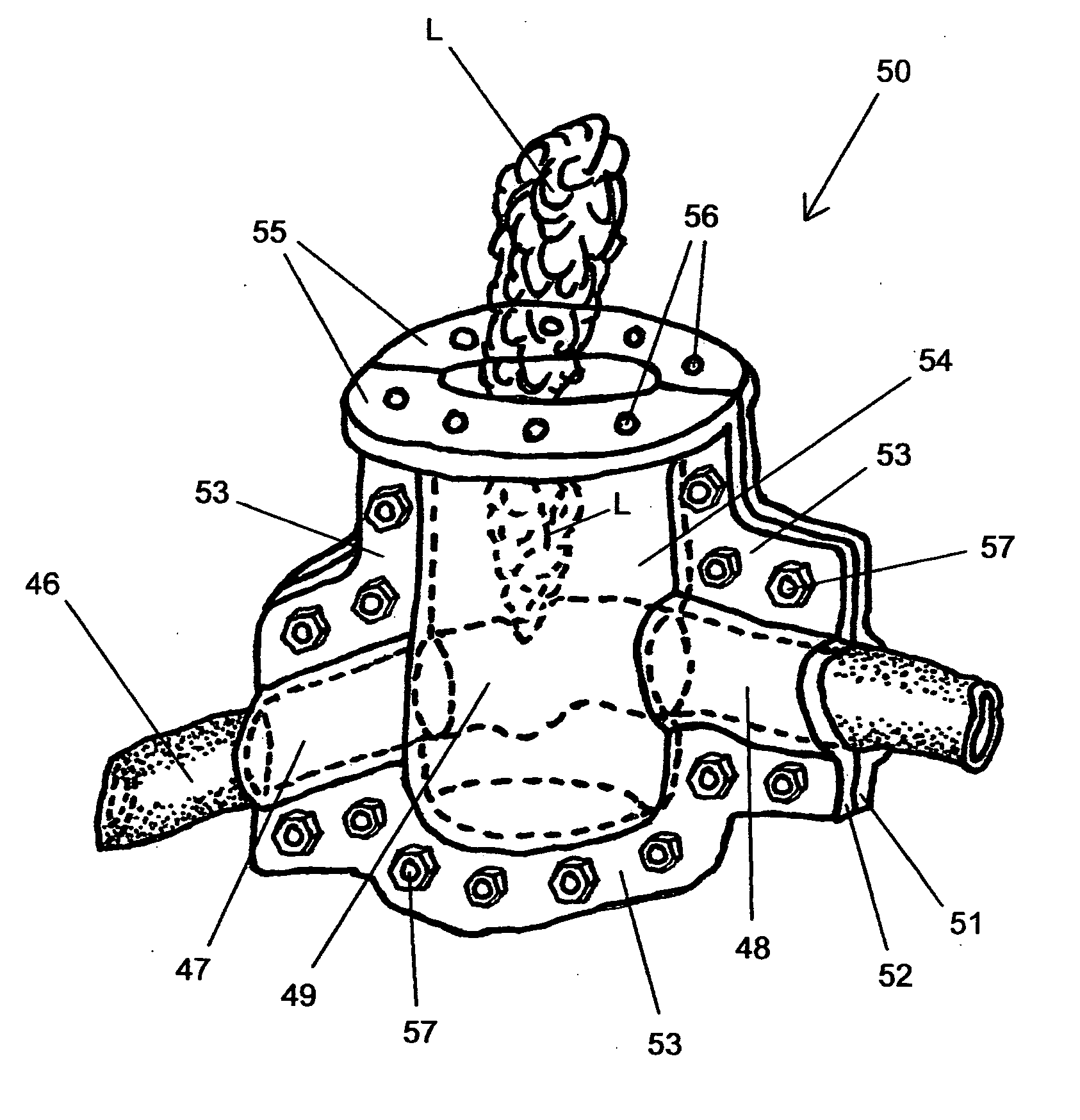
From the earliest days of the spill,
confusion and
frustration emerged from the fact that everyone could see, in the
live video feed of the leaking well, a two-part pipe flange fixture at the top of the BOP.
But early on, there is strong evidence to suggest that BP and other experts were not sure if the top half of the flange could be removed at all, or if it could be done safely.
This kind of thing had never been attempted in
deep water, and BP had no established procedure for doing it.
Moreover, there may have been concerns about whether removing the top flange would damage the BOP, and make things a lot worse.
Experts had realized that the BOP may have already been damaged during the accident, in both known and unknown ways.
[14][15] Particular attention was given to interventions that might be too intrusive on the BOP, or on the surrounding rock, running the risk of making things worse.
This discovery had been a surprise to BP, and further raised worries, by both experts and the public, that the true state of things inside the BOP was not fully understood.
[17] There may also have been concerns that the trapped
drill pipes, being in contact with both the top flange and the partially shut-off area within the BOP, might make it dangerous to shift the position of the top flange.
It was a highly complex procedure.
[19] BP wasn't sure they would actually be able to unbolt the flange at all.
Summarizing then, we see that (1) there is no applicable technique found in the prior art which permits attachment onto severely distorted riser pipe, or a similar irregular surface, (2) a comparable lack of technique may also exist in the matter of rigidly attaching
machine-tool platforms onto irregular surfaces, so as to facilitate precise cuts of damaged pipes, and (3) the flange removal process, while it has the potential of giving a tight seal, involves intruding into an unknown state of the BOP, and thus carries with it significant risks of damaging the BOP and thereby making the leak worse.

