Panel-cooled submerged combustion melter geometry and methods of making molten glass

Active Publication Date: 2011-12-22
MANVILLE JOHNS
View PDF10 Cites 111 Cited by
  • Summary
  • Abstract
  • Description
  • Claims
  • Application Information

AI Technical Summary

Benefits of technology

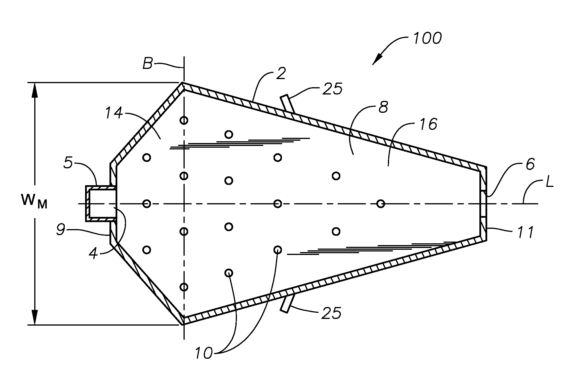
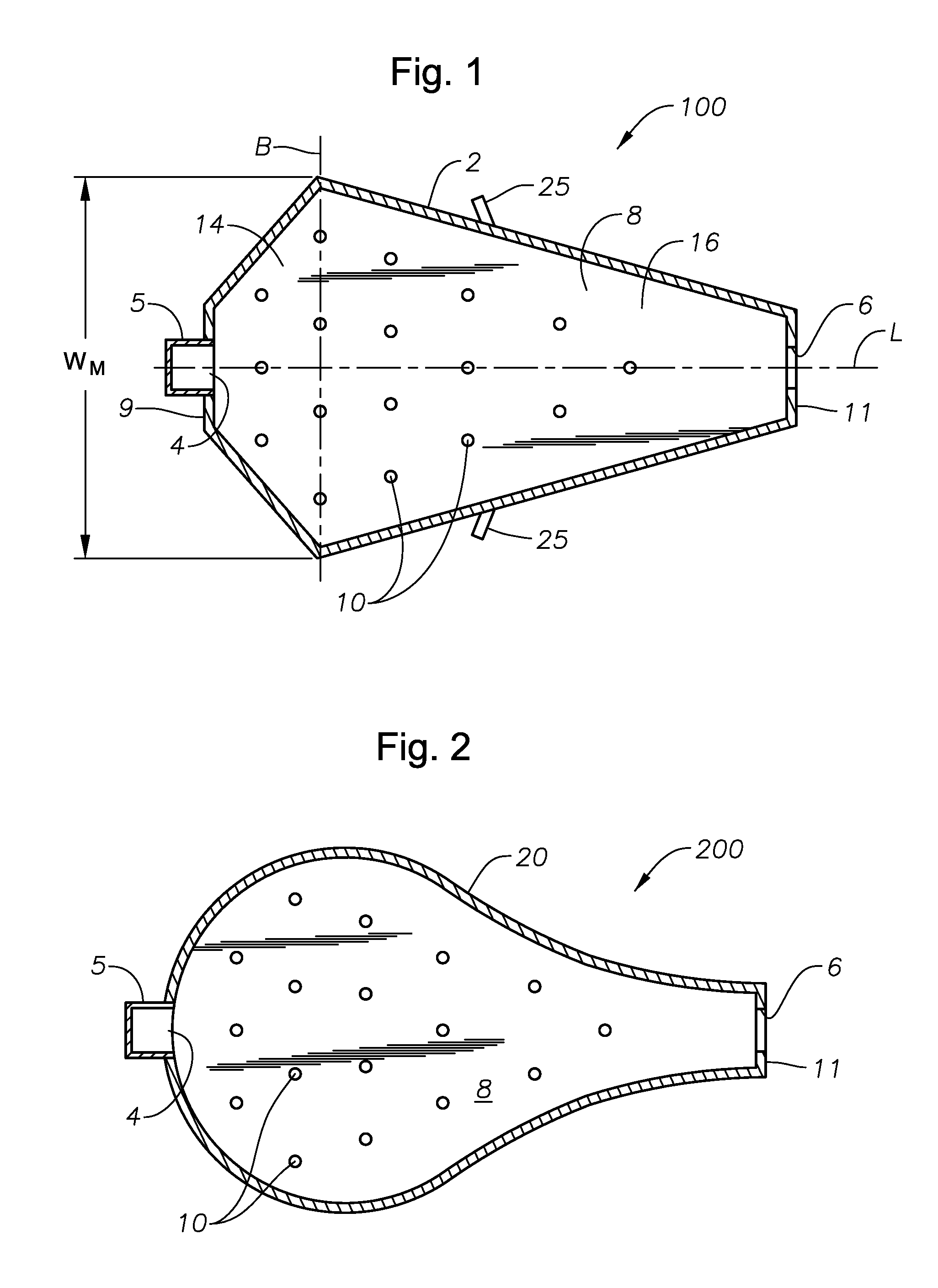
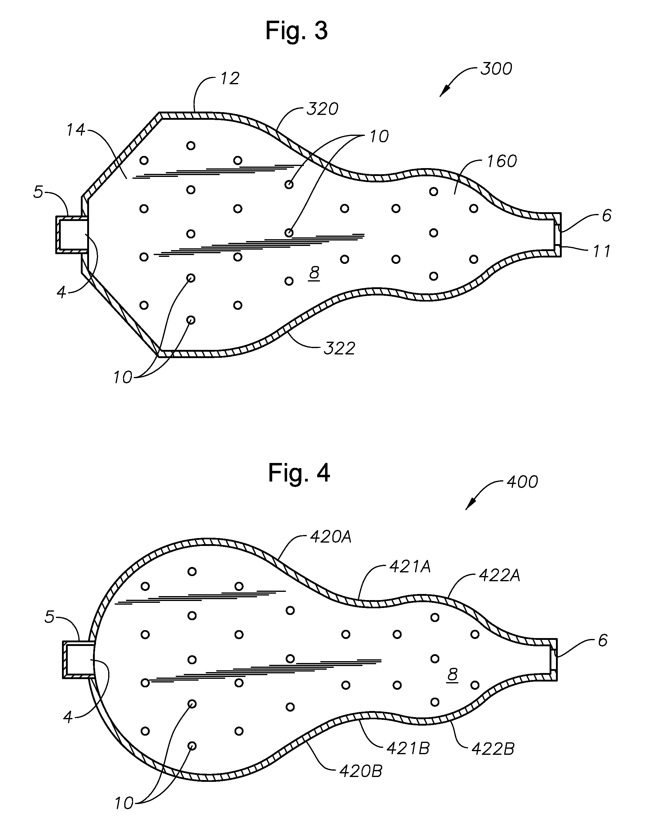
[0008]In accordance with the present disclosure invention, melters and processes of using them are described that reduce dead flow (stagnant) regions and take advantage submerged combustion burners. The melters of the present disclosure are at least partially constructed using cooled refractory panels, which allows construction of melters having configurations that reduce or avoid the dead flow corner regions prevalent in traditional glass melter rectangular designs by eliminating the dead (low or stagnant) corners of the known rectangular melter configurations. In certain melter embodiments according to this disclosure, the side walls are angled so that the flow spacing for molten glass narrows toward the discharge (mol

Problems solved by technology

However, there are significant dead (low flow or stagnant) regions that result from the rectangular construction.
However, using submerged combustion burners does not alleviate dead flow reg

Method used


Image

  • Panel-cooled submerged combustion melter geometry and methods of making molten glass
  • Panel-cooled submerged combustion melter geometry and methods of making molten glass
  • Panel-cooled submerged combustion melter geometry and methods of making molten glass

Examples


Embodiment Construction

[0038]In the following description, numerous details are set forth to provide an understanding of various melter apparatus and process embodiments in accordance with the present disclosure. However, it will be understood by those skilled in the art that the melter apparatus and processes of using same may be practiced without these details and that numerous variations or modifications from the described embodiments may be possible which are nevertheless considered within the appended claims.

[0039]Referring now to the figures, FIGS. 1-5 are plan views, with parts broken away, of five melter embodiments in accordance with the present disclosure. FIG. 6 is a side cross-sectional view of the melter apparatus illustrated in FIG. 1. The same numerals are used for the same or similar features in the various figures. In the plan views illustrated in FIGS. 1-5, it will be understood in each case that the roof and exhaust chimney are not illustrated in order to illustrate more clearly the key...


PUM

PropertyMeasurementUnit
Areaaaaaaaaaaa
Areaaaaaaaaaaa
Flow rateaaaaaaaaaa

Abstract

A melter apparatus includes a floor, a ceiling, and a substantially vertical wall connecting the floor and ceiling at a perimeter of the floor and ceiling, a melting zone being defined by the floor, ceiling and wall, the melting zone having a feed inlet and a molten glass outlet positioned at opposing ends of the melting zone. The melting zone includes an expanding zone beginning at the inlet and extending to an intermediate location relative to the opposing ends, and a narrowing zone extending from the intermediate location to the outlet. One or more burners, at least some of which are positioned to direct combustion products into the melting zone under a level of molten glass in the zone, are also provided.

Description

BACKGROUND OF THE INVENTION[0001]1. Field of Invention[0002]The present invention relates generally to the field of combustion furnaces and methods of use, and more specifically to improved submerged combustion melters and methods of use in producing molten glass.[0003]2. Related Art[0004]Glass melting furnaces have traditionally been of rectangular shape due to the issue of construction with refractory blocks and ability to control the flow of the molten glass through the melter. (Some all-electric designs are circular, such as Pochet and SORG VSM designs.) However, there are significant dead (low flow or stagnant) regions that result from the rectangular construction.[0005]Submerged combustion has been proposed in several patents for application in commercial glass melting, including U.S. Pat. Nos. 4,539,034; 3,170,781; 3,237,929; 3,260,587; 3,606,825; 3,627,504; 3,738,792; 3,764,287; 6,460,376; 6,739,152; 6,857,999; 6,883,349; 7,273,583; 7,428,827; 7,448,231; and 7,565,819; and p...

Claims


Application Information

Patent Timeline
IPC IPC(8): C03B5/26C03B5/00
CPCC03B5/04C03B5/2353C03B5/2356C03B2211/70C03B2211/23C03B5/235C03B2211/22C03B5/44Y02P40/57C03B5/202C03B5/225F23C5/08F23D14/22F23D14/32F23C2205/10F23C2205/20B05B1/3405C03B2211/40Y02P40/50
Inventor HUBER, AARON MORGAN
Owner MANVILLE JOHNS
Why Eureka
Try Eureka