
Method and control device for operating an internal combustion engine

a technology of internal combustion engine and control device, which is applied in the direction of electrical control, process and machine control, instruments, etc., can solve the problem that the torque accuracies required of the abovementioned drive concepts cannot be fulfilled, and achieve the effect of increasing accuracy

Inactive Publication Date: 2011-12-22
ROBERT BOSCH GMBH
View PDF7 Cites 0 Cited by
  • Summary
  • Abstract
  • Description
  • Claims
  • Application Information

AI Technical Summary

Benefits of technology

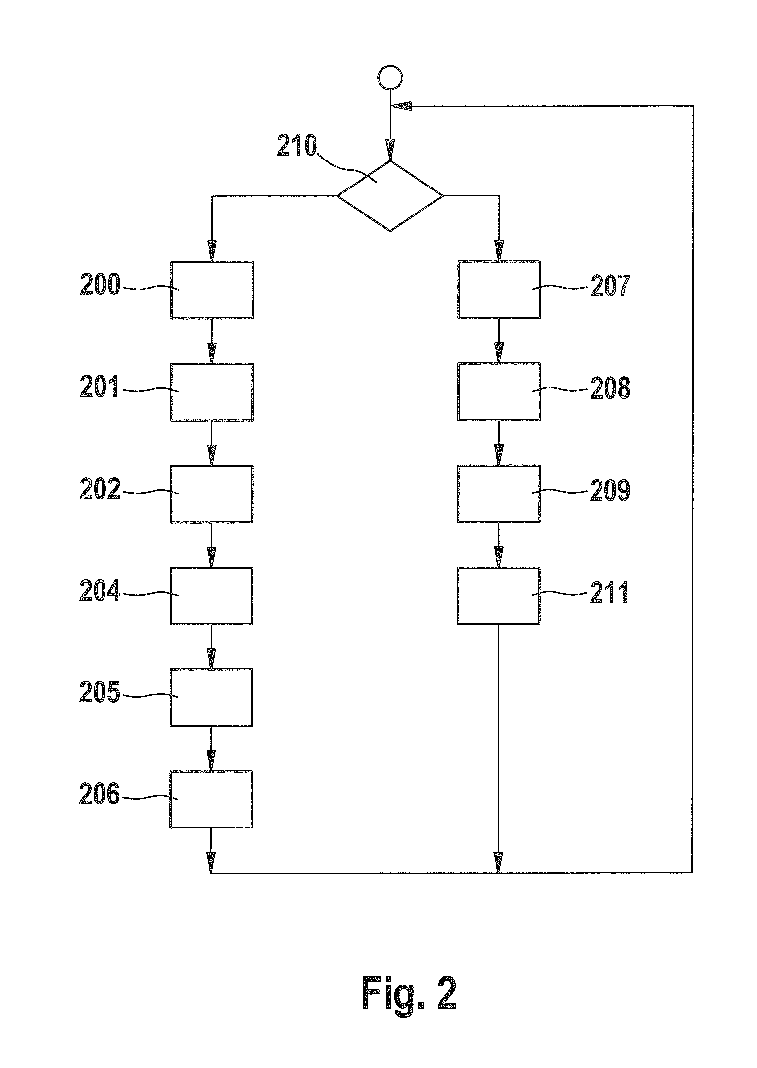
[0006]Accordingly, a method for operating an internal combustion engine is provided, in which first a setpoint value is specified of a first fuel injection quantity for a first combustion cycle of the internal combustion engine, and the first fuel injection quantity is injected. During the first combustion cycle, a combustion pressure is ascertained. In a further step, a setpoint value of a second fuel injection quantity for a second combustion cycle of the internal combustion engine is ascertained, based on the combustion pressure. This makes possible adjusting the setpoint value of the second fuel injection quantity according to the quality control in such a way that a desired torque is achieved at great accuracy.
[0008]According to one preferred refinement of the method according to the present invention, the injecting of the first fuel injection quantity and the ascertaining of the combustion pressure take place repeatedly for a plurality of combustion cycles. The ascertaining of the setpoint value of the second fuel injection quantity takes place based on the corresponding plurality of ascertained combustion pressure values during the plurality of the respective combustion cycles. The accuracy is further increased thereby, since a possible influence of statistical fluctuations of the combustion pressure is reduced via the plurality of combustion cycles.
[0009]According to one preferred refinement, a step of ascertaining is further provided as to whether the internal combustion engine is in a specifiable operating state. In this instance, the ascertaining of the combustion pressure takes place only if the internal combustion engine is in the specifiable operating state. This makes it possible further to increase the accuracy of the torque achieved, by specifying, as the specifiable operating state, such an operating state as the one in which an internal efficiency of the internal combustion engine is particularly exactly known.
[0010]According to another preferred refinement, the step of ascertaining the second fuel injection quantity includes sub-steps of calculating an actual value of the first fuel injection quantity based on the combustion pressure, of ascertaining a correction factor by comparing the specified first fuel quantity to the actual value, of specifying the setpoint value of the second fuel injection quantity, and of correcting the setpoint value using the correction factor. This calculating method is particularly efficient and simple to implement, especially in a control unit having limited calculating capacity.
[0012]The current fuel injection parameter preferably has a current fuel pressure in a fuel pressure accumulator of the internal combustion engine and / or a current fuel injection pattern. This makes possible a further increase in accuracy, since the correction factor ascertained in typical internal combustion engines demonstrates a dependence on the fuel pressure in the fuel pressure accumulator of the internal combustion engine and of the fuel injection pattern.

Problems solved by technology

In this context, in particular, tolerances of the injection quantities in multiple injections, having high variability of the injection patterns and injection intervals, may become so great that the torque accuracies required of the abovementioned drive concepts can no longer be fulfilled.

Method used


Image

  • Method and control device for operating an internal combustion engine
  • Method and control device for operating an internal combustion engine
  • Method and control device for operating an internal combustion engine

Examples


Embodiment Construction

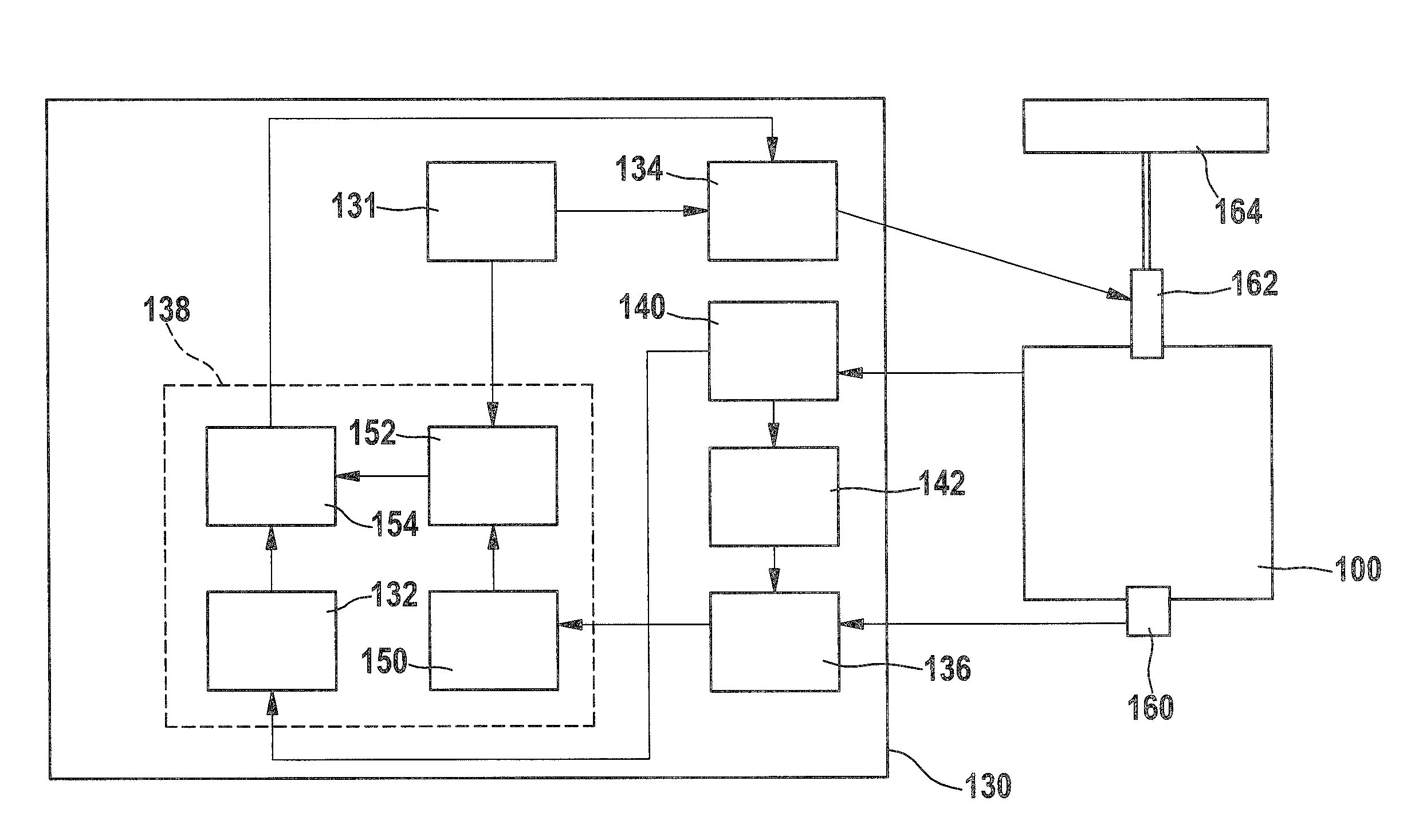
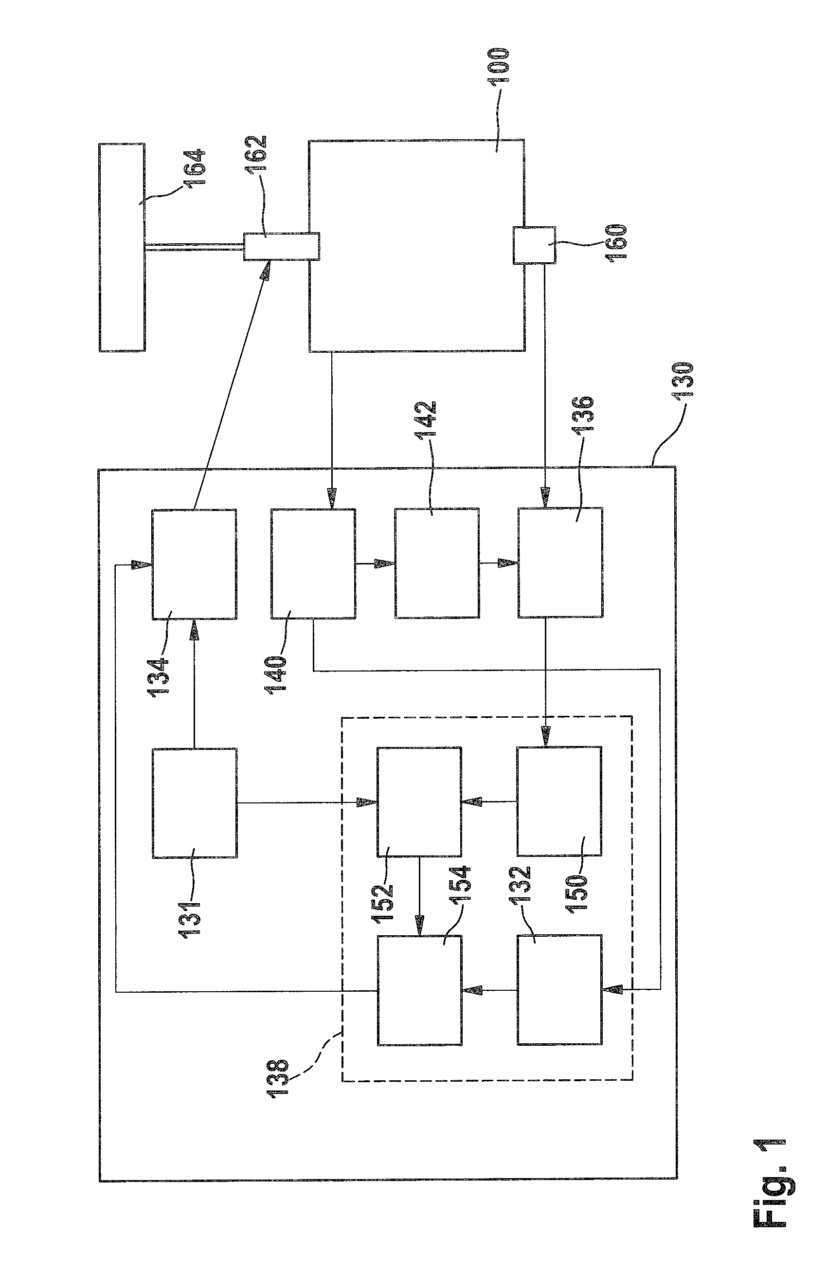
[0015]In a schematic block diagram, FIG. 1 shows quality-controlled internal combustion engine 100 which, for instance, may be developed as a Diesel-powered engine. Internal combustion engine 100 has a fuel injection system having a fuel pressure accumulator 164 (rail), which is connected, via a pressure line, to a fuel injector 162 for injecting fuel that is under high pressure in fuel pressure accumulator 164 into a combustion chamber (not shown) of internal combustion engine 100. Internal combustion engine 100 has a combustion pressure sensor 160 for measuring a combustion pressure that is created after the ignition of the mixture obtained from the fuel injected by fuel injector 162.

[0016]A control unit 130 for controlling internal combustion engine 100 is connected via a plurality of signal paths to internal combustion engine 100. Control unit 130 has a control stage 134 for controlling fuel injector 162 in such a way that, depending on a fuel quantity signal received from the c...


PUM


Abstract

In a method for controlling operation of an internal combustion engine using a control device, a setpoint value of a first fuel injection quantity is specified for a first combustion cycle, and the first fuel injection quantity is injected. A combustion pressure is ascertained during the first combustion cycle, and in a further step, a setpoint value of a second fuel injection quantity is ascertained for a second combustion cycle based on the combustion pressure.

Description

BACKGROUND OF THE INVENTION[0001]1. Field of the Invention[0002]The present invention relates to a method for operating an internal combustion engine, especially a quality-controlled internal combustion engine, and also to a computer program product for executing the method and a control device for an internal combustion engine.[0003]2. Description of the Related Art[0004]The demands on modern internal combustion engines, particularly those used in vehicles, rise continuously, conditioned upon both legal boundary conditions with respect to admissible emission limits and increased expectational attitudes of end users with respect to travel comfort, smooth running and consumption. One fundamental approach to fulfilling these requirements is an exact control of fuel combustion. This takes place, for instance, in so-called quality-controlled internal combustion engines, which work according to the Diesel combustion method or a lean Otto combustion method, via a targeted, load-dependent ...

Claims


Application Information

Patent Timeline
Patent Type & Authority Applications(United States)
IPC IPC(8): F02M51/00
CPCF02D41/3005F02D35/023
Inventor BROX, OLIVER
Owner ROBERT BOSCH GMBH
Learn More