Bladeless wind power generator

a bladeless wind power and generator technology, applied in piezoelectric/electrostrictive/magnetostrictive devices, piezoelectric/electrostriction/magnetostriction machines, climate sustainability, etc., can solve the problems of noisy, intolerant to damage, inefficient and expensive systems to construct and maintain, etc., to achieve more efficient piezoelectric materials

Active Publication Date: 2011-12-22
LU WEIXING +1
View PDF0 Cites 10 Cited by
  • Summary
  • Abstract
  • Description
  • Claims
  • Application Information

AI Technical Summary

Benefits of technology

[0006]The present invention is a new approach to converting wind motion to electrical power. The approach is based on an adaptation of the piezoelectric effect—a well known property of certain materials to produce electrical power when they undergo strain and stress. For example, in devices such as microphones, sound vibrations can create enough stress and strain on piezoelectric crystals to generate electric current. Based on recent breakthroughs in nanotechnology, new, low-cost, micro-sized crystals can now be assembled to create more efficient piezoelectric materials.
[0007]A first embodiment of this invention incorporates piezoelectric materials as components inserted into the side walls of a uniquely designed air jet tunnel to form a bladeless Wind Energy to Power (WEP) system. More specifically, the system uses (1) a thin brass layer, sandwiched between two Poly Vinylidene Fluoride (PVDF) layers to form a cantilever with high piezoelectric conversion; efficiency (2) a unique air jet tunnel and phononic cascade configuration with high coefficient of performance; and (3) a compact, modular power unit design.
[0008]The first embodiment of the present invention has the following advantages over the prior art:

Problems solved by technology

These systems are inefficient and expensive to construct and maintain.
They are also noisy, intolerant to damage, and relatively difficult to transport and assemble1,2.
They can also impose safety and environmental concerns.
Unfortunately, a compact, modular, bladeless wind energy system does not exist although some approaches have been proposed.
Air-liquid and liquid-solid interfaces have to be included in such system, resulting in very low conversion efficiency and high cost of manufacture.
It is obvious that most of the wind's kinetic energy is lost in order to move the charged aerosol from one electrode to another.
However, this approach also exhibits low efficiency and high cost because it requires an additional energy-absorbing process to drive the liquid flow in the microchannels where only a weak electric current is induced due to the presence of an electrical double layer in the interface between the liquid and microchannel walls.

Method used


Image

  • Bladeless wind power generator
  • Bladeless wind power generator
  • Bladeless wind power generator

Examples


Embodiment Construction

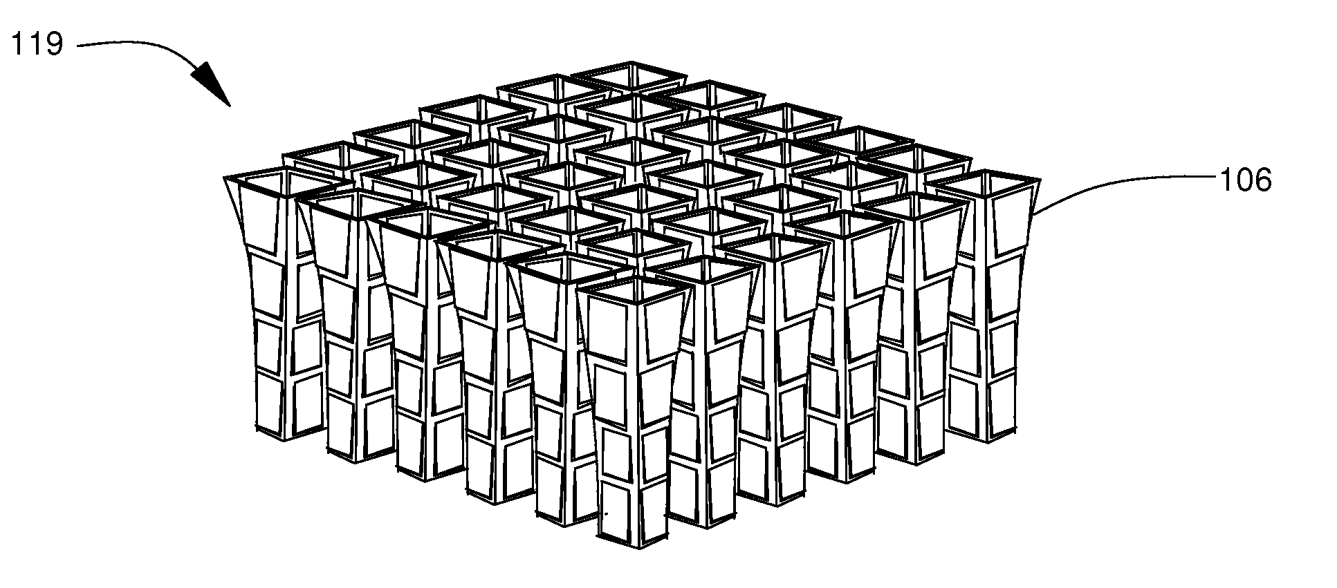
[0066]The term cascaded frame, in this detailed description, means that the frame has cross-sections that decrease in size moving from the air intake opening 122 to the air outtake end 124. The term air flow energy is interpreted as wind energy. If a part number in the figures refers to multiple parts, only one or two parts may be assigned the part number, and the same part number may be used for the singular part and the same multiple parts in the figures. The same part number may be used for a generic term such as the piezoelectric material 128 and a specific implementation such as polyvinylidene fluoride (PVDF).

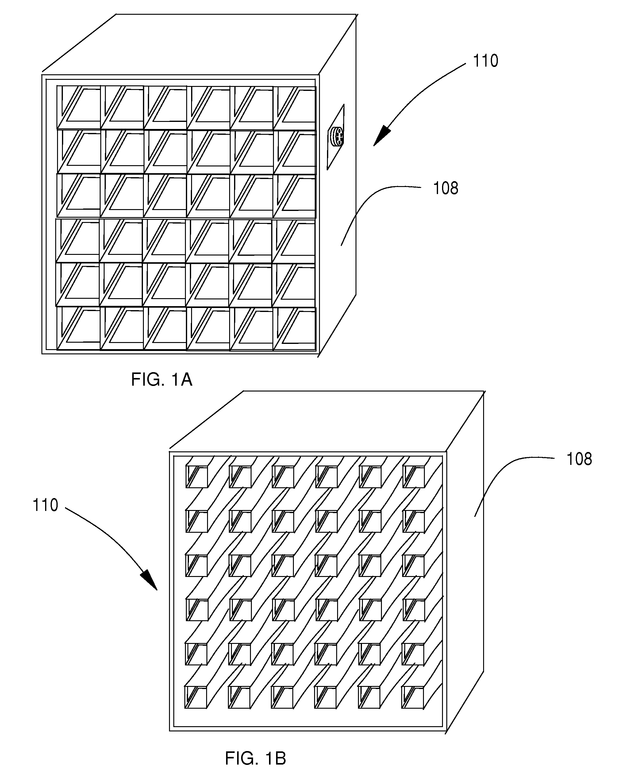
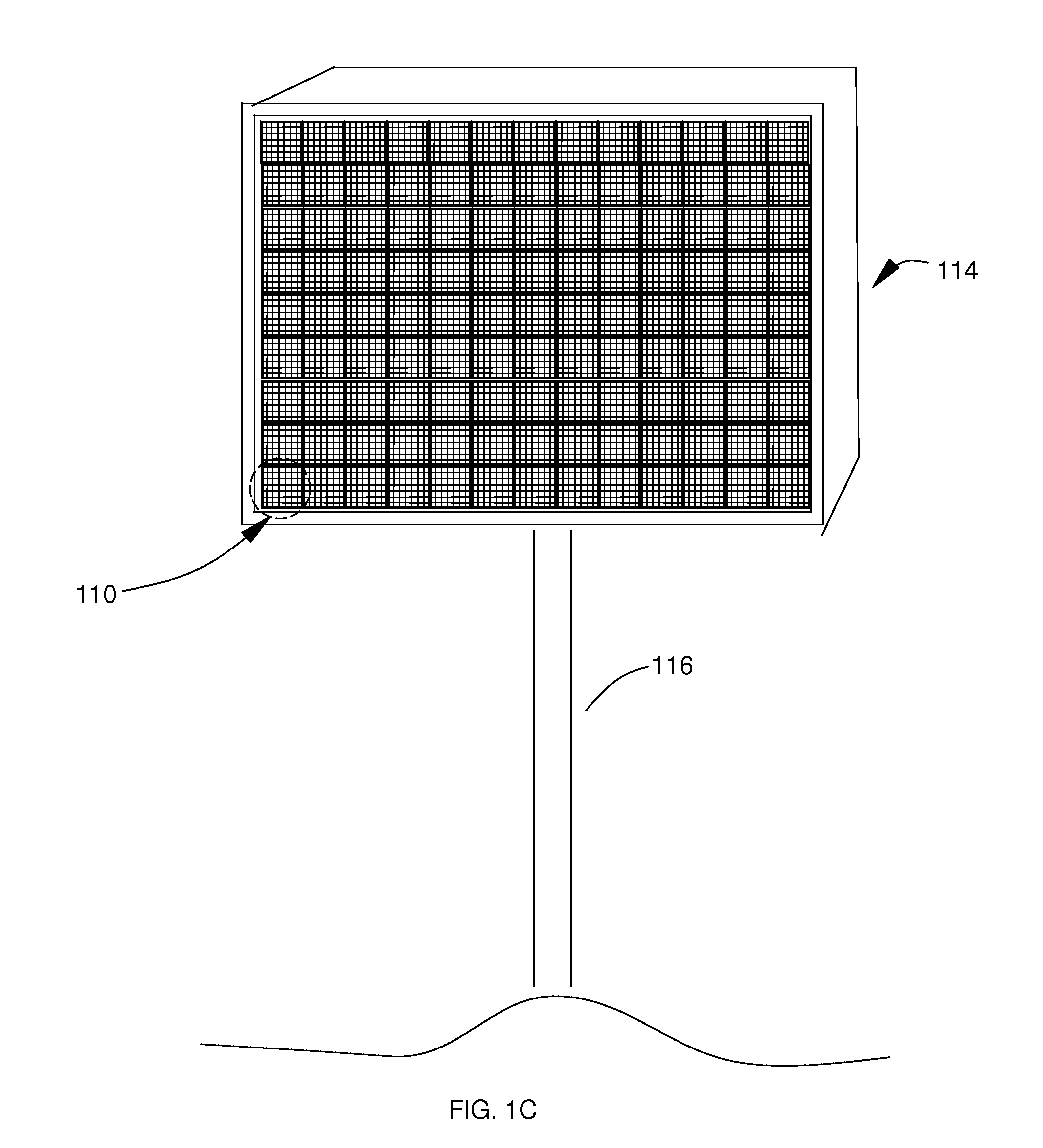
[0067]FIGS. 1A through 1E illustrates an overview and the use of the air jet tunnels of a first embodiment of the present invention. FIGS. 2A and 2B illustrate a proprietary design of a cantilever 102 used in the embodiment. FIG. 3A illustrates the configuration of the air jet tunnel 106 with cascading cantilever array 117 on the side walls 120 showing the path of air flow...


PUM


Abstract

In a first embodiment, a wind to energy conversion system is constructed out of a number of modular power units (110), each modular power unit (110) comprised of 36 air jet tunnels (106). Each air jet tunnel (106) is constructed using a cantilever array mounted in a cascaded frame (104) with each cantilever (102) attached on one edge to a window edge of the frame (104). The cantilever (102) is constructed of a brass (130) layer sandwiched between two layers, each layer composed of an electrode (126) attached to a Poly Vinylidene Fluoride (PVDF) (128) layer. Each modular power unit (110) is mounted in a case (108), and a set of cases are mounted in a panel (114) attached to a pedestal (116). The cantilever arrays (117) are wired together into electrical regulating circuits that generate power with a high wind to power conversion efficiency. Other embodiments are presented.

Description

[0001]This application claims the benefit of the U.S. Provisional Patent Application No. 61 / 378,068 filed Aug. 30, 2010 by the present inventors. This provisional patent application is incorporated herein in its entirety by reference.TECHNICAL FIELD[0002]The present invention relates generally to generating electrical power from wind motion energy.BACKGROUND OF THE DISCLOSURE[0003]Current wind power generators generally employ wind turbines and electric motors to generate electricity. These systems are inefficient and expensive to construct and maintain. They are also noisy, intolerant to damage, and relatively difficult to transport and assemble1,2. They can also impose safety and environmental concerns. Unfortunately, a compact, modular, bladeless wind energy system does not exist although some approaches have been proposed. The potential advantages to its development include reduced noise, size, and cost combined with improved portability, efficiency, and cost-effectiveness.[0004...

Claims


Application Information

Patent Timeline
Patent Type & Authority Applications(United States)
IPC IPC(8): H02N2/00
CPCH02N2/181Y02B10/30H02N2/185
Inventor LU, WEIXINGROBERTS, ALLAN
Owner LU WEIXING
Why Eureka
Try Eureka